Search the Community
Showing results for tags 'wiring'.
-
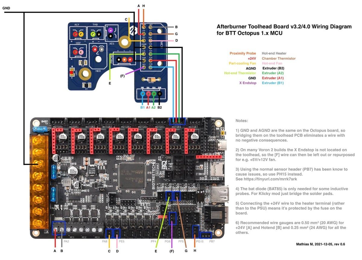
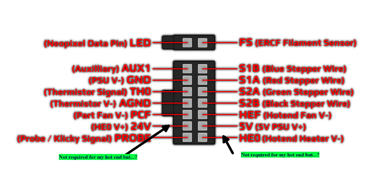
 A wiring diagram for the Afterburner Toolhead breakout board connecting to and BTT (BigTreeTech) Octopus 1.x board. This is teh latest diagram after 4 different revisions with community involvement and support NOTES: GND and AGND are the same on the Octopus board, so bridging them on the toolhead PCB eliminates a wire with no negative consequences. On many Voron 2 builds the X endstop is not located on the toolhead, so the [F] wire can then be left out or repurposed for e.g. +5V/+12V fan. Using the normal sensor header (PB7) has been know to cause issues, so use PH15 instead. See Why isn't my probe working on the Octopus? The bat diode (BAT85) is only needed for some inductive probes. For Klicky mod just bridge the solder pads. Connecting the +24V wire to the heater terminal (rather than to the PSU) means it's protected by the fuse on the board. Recommended wire gauges are 0.50 mm2 (20 AWG) for +24V [A] and Hotend [B] and 0.25 mm2 (24 AWG) for all the others
-
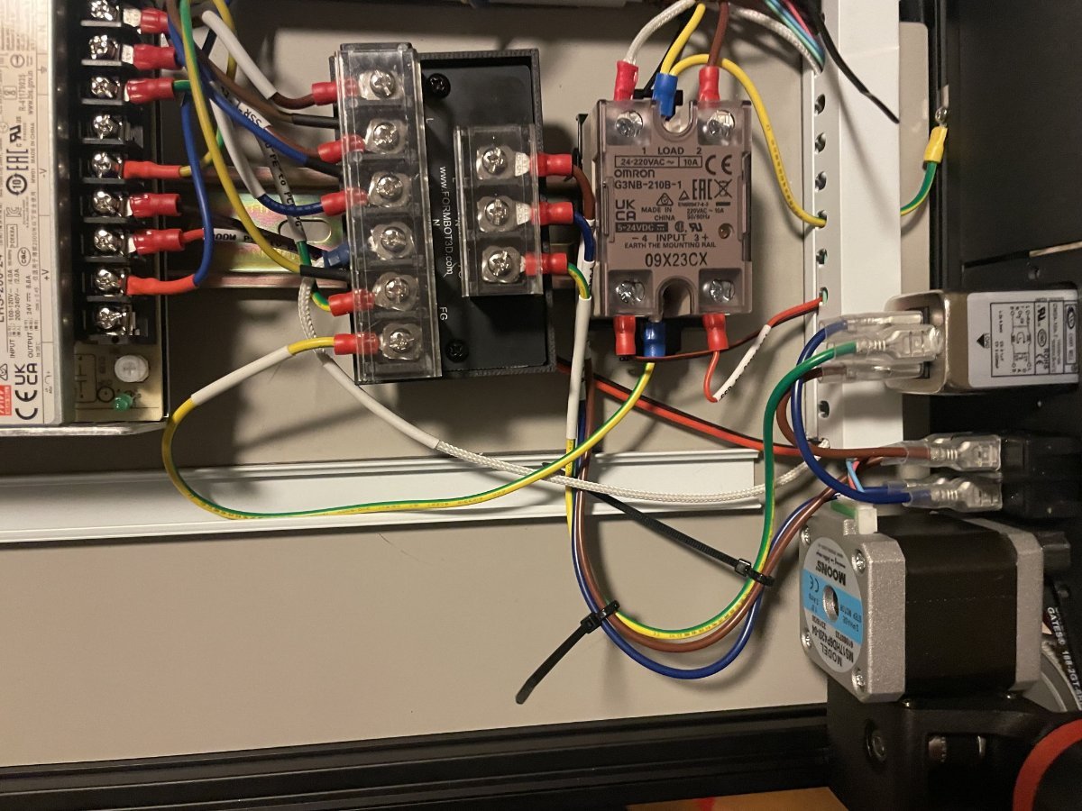
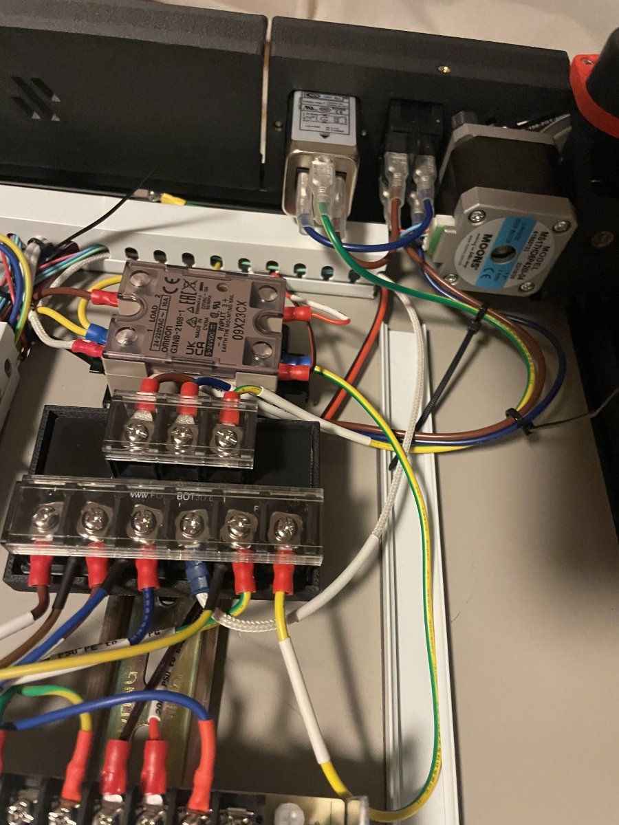
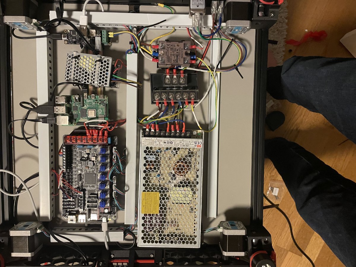
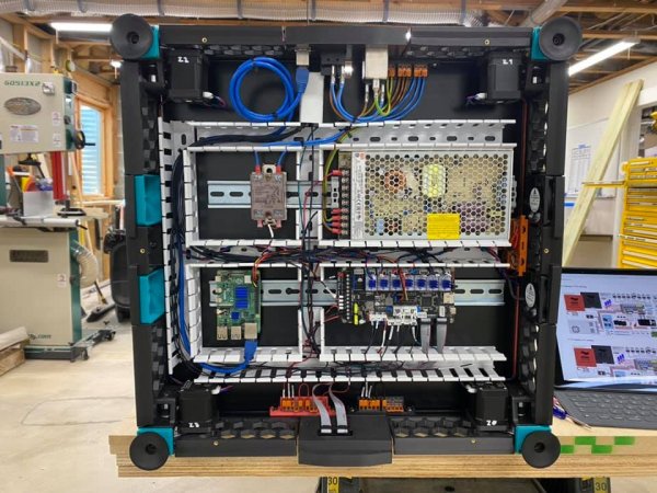
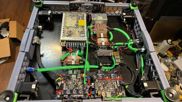
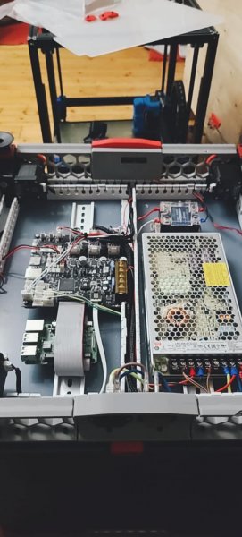
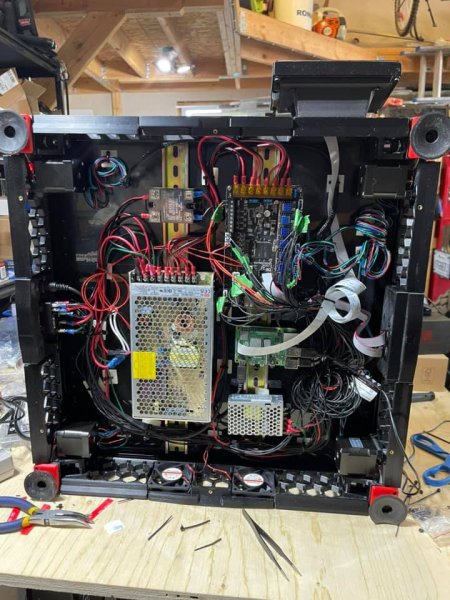
 I almost finished building my Voron 2.4 formbot kit. Just the sidepanels and exhaust fans are missing, I am using sb2240 on stealthburner wired to u2c. My question is, in the pictures below, is the wiring correct and also any tips of what I should unplug on first startup?
-
 Hello Everyone: I am slowing getting my Voron 2.4r build done and I have entered the wiring phase of the build. I have a Phateus Rapido hot end installed, which according to someone, somewhere, stated that it draws slightly more than 100 watts during startup. I could limit that current draw in the config, but I would prefer not to. I bring this up because the Hartk PCB is rated at 50 watts. In light of this I am running two seperate 20 gauge wires for the hot end which will bypass the PCB's. These two wires will be utilizing the bed output on my Octopus v1.1 board. The question is this... I need 24 volts to the two piece tool head. Where should I get that power from? Would it be from the Octopus or would it be from the 24v power supply. I am assuming it should come from the Octopus, and if so, what output on the Octopus? I would also assume that that 24v should go to the HEO V+ and HEO V- on the Hartk because that is essentially the 24v supply for the head? Yes, when it comes to electronics, I am a noob but learning heaps and enjoying every minute of it. Thank you!
-

ldo Trident 300 kit - x gantry movement with cable chains
polygonprint posted a question in Voron 1- Questions
Hello all. I'm building a ldo Trident 300 kit and am at the wiring stage of the build. Move of the tool head along the x gantry is smooth without the cable chains and wiring but once I add those the movement binds up towards the end of the x travel (opposite side from the endstop). My cable chain seems long enough but to me it seems as though the chain radius is too small as it moves up and over the printed xy joints and fasteners. Hope that makes sense... I should take some pics and post. I have tried adjusting lengths etc. but the movement of the tool head gets a bit jerky towards the end. I was hoping somebody else may have had this problem and solved it. Thanks all! -
 does anyone has any files or pics they could share involving the formbot trident build that shows all wiring with the wagos. im struggling with not being able to find info. i have the octopus v1.1. thanks in advance
 -
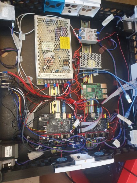
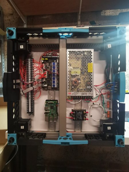
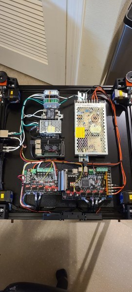
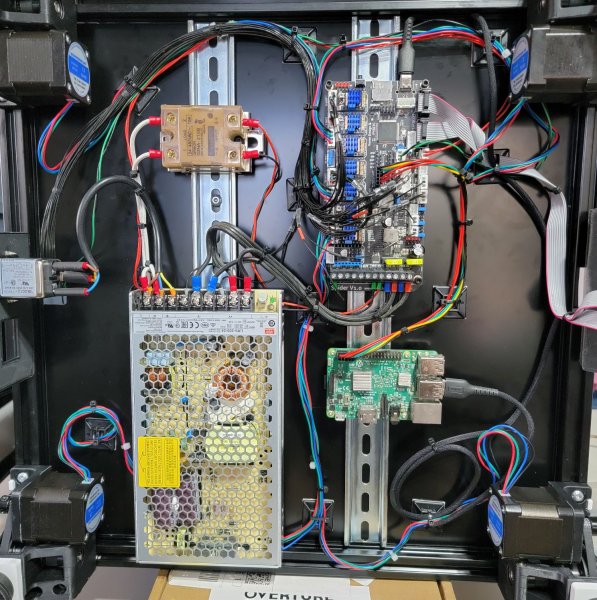
From the album: 2.4 Wiring Gallery
-
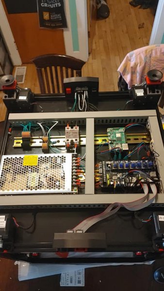
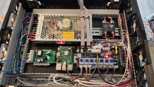
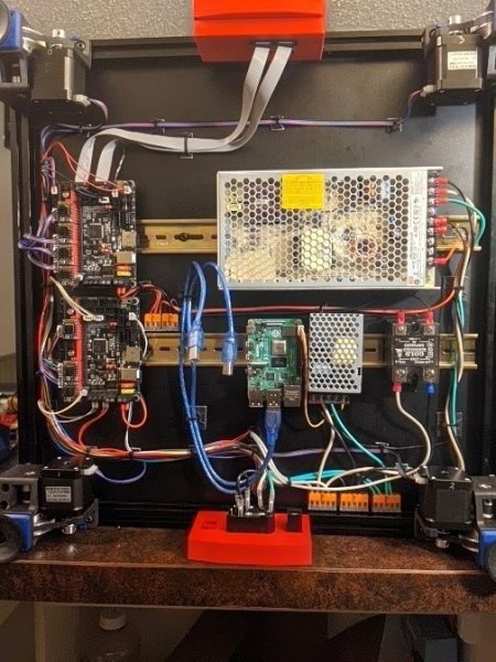
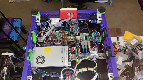
From the album: 2.4 Wiring Gallery
-
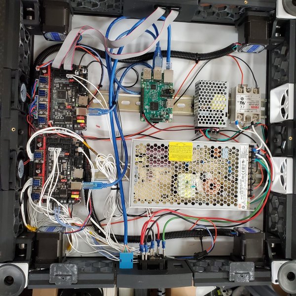
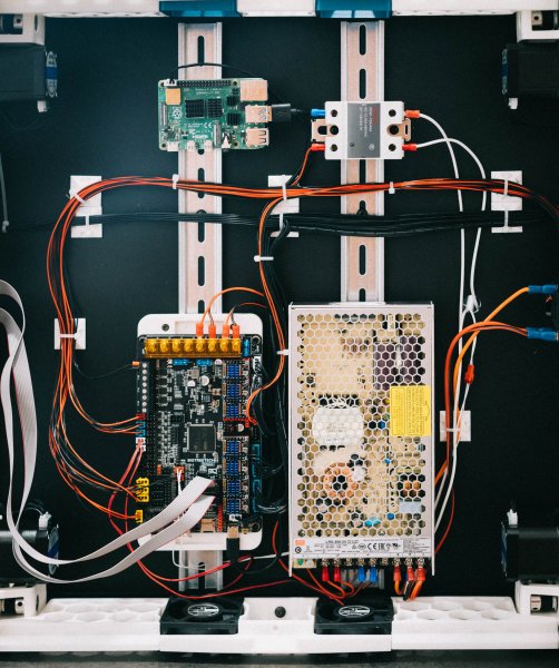
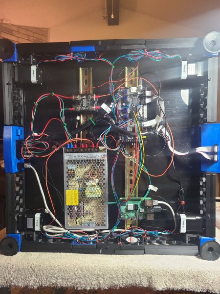
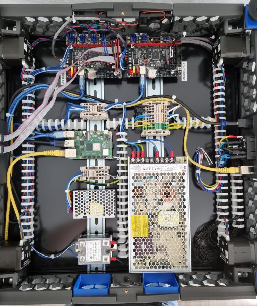
From the album: 2.4 Wiring Gallery
-
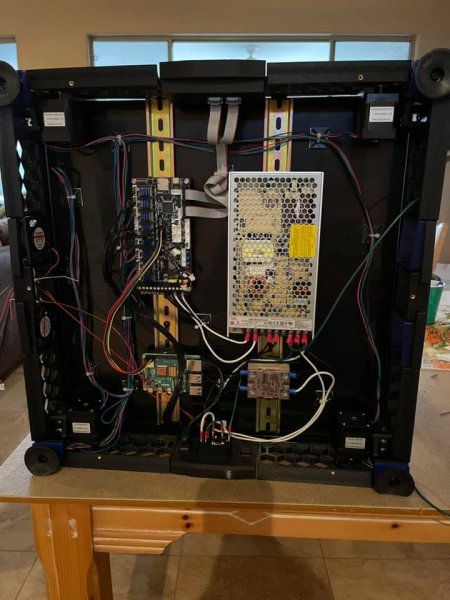
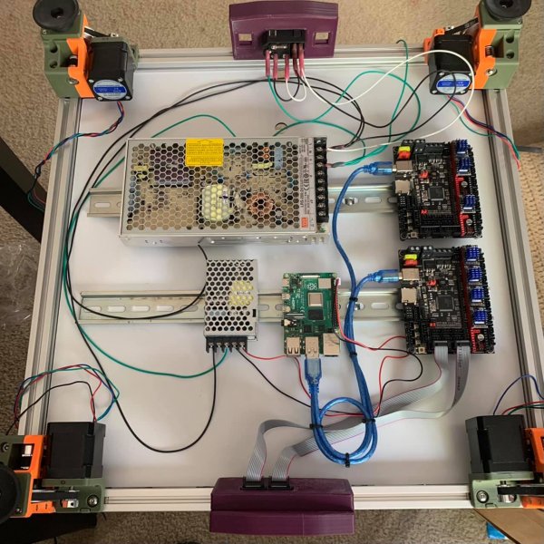
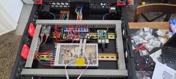
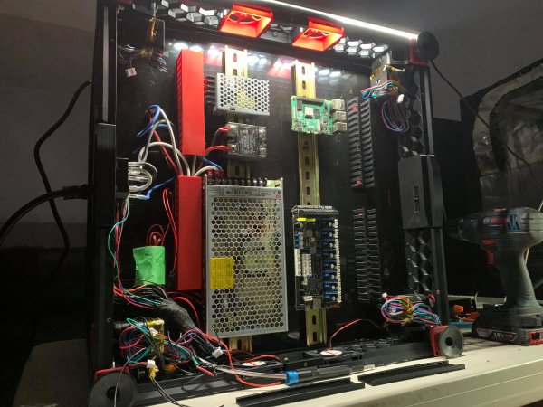
From the album: 2.4 Wiring Gallery
-
From the album: 2.4 Wiring Gallery
-
From the album: 2.4 Wiring Gallery
-
From the album: 2.4 Wiring Gallery
-
From the album: 2.4 Wiring Gallery
-
From the album: 2.4 Wiring Gallery
-
From the album: 2.4 Wiring Gallery
-
From the album: 2.4 Wiring Gallery
-
From the album: 2.4 Wiring Gallery
-
From the album: 2.4 Wiring Gallery
-
From the album: 2.4 Wiring Gallery
-
From the album: 2.4 Wiring Gallery
-
From the album: 2.4 Wiring Gallery
-
From the album: 2.4 Wiring Gallery
-
From the album: 2.4 Wiring Gallery
-
From the album: 2.4 Wiring Gallery
-
From the album: 2.4 Wiring Gallery