Search the Community
Showing results for tags 'electronics'.
Found 4 results
-

Version 1.0.0
10 downloads
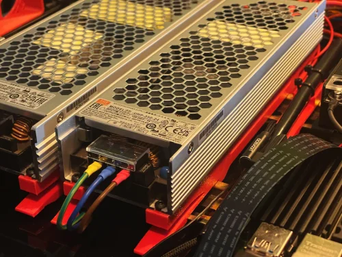
A DIN Rail Mount for a Mean Well UHP-500-XX Power Supply that attaches across two DIN Rails. Print Instructions: I've used the usual Voron 0.2mm Layer Height, 4x Perimeter, 5x Top / Bottom Layers, and 40% Infill Settings which should work for anything using Heat Set Inserts. The Models come with in the Slicer added Mouse Ears to help with bed Adhesion - If you don't need them just remove the “Generic-Disk” BOM ( for a Set of Two ) : 4x Voron Style M3x4mm Heat Set Inserts 8x M3x10mm Button Head Cap Screws 4x M3 Washers Assembly: Install two M3x10mm Button Head Cap Screws with the M3 Washers ( marked in blue ) into the bottom of the Mounts acting as Reinforcements for the Hooks - The PSUs turned out to be surprisingly heavy and I didn't want to risk the weight of them pulling down on the Hooks causing the latter to become loose. Install two Voron Style M3x4mm Heat Set Inserts ( marked in blue ). The one behind the Securing Latch is a bit hard to get into - Use a longer M3 to help pull it in. Attach the Mean Well UHP-500-XX Power Supply to the Mounts using the remaining M3x10mm Button Head Cap Screws. Attach the Assembly to the DIN Rails with a sliding motion while pressing down at the end with the Securing Latches. To remove the Assembly, pull the Latches slightly up followed by sliding it back out. Word of Caution: This Design requires the distance between the DIN-Rails to be of proper length! Too far apart and the rear Hook will prevent the Locking Mechanism from properly seating onto the front Rail. Too close together and the rear Hook might not catch. As such perhaps consider using the Mounts themselves with setting up the required distance between the DIN-Rails. -
Version 1.0.0
22 downloads
A DIN Rail Mount for a Mean Well UHP-350-XX Power Supply that attaches across two DIN Rails. Print Instructions: I've used the usual Voron 0.2mm Layer Height, 4x Perimeter, 5x Top / Bottom Layers, and 40% Infill Settings which should work for anything using Heat Set Inserts. The Models come with in the Slicer added Mouse Ears to help with bed Adhesion - If you don't need them just remove the “Generic-Disk” BOM ( for a Set of Two ) : 4x Voron Style M3x4mm Heat Set Inserts 8x M3x10mm Button Head Cap Screws 4x M3 Washers Assembly: Install two M3x10mm Button Head Cap Screws with the M3 Washers ( marked in blue ) into the bottom of the Mounts acting as Reinforcements for the Hooks - The PSUs turned out to be surprisingly heavy and I didn't want to risk the weight of them pulling down on the Hooks causing the latter to become loose. Install two Voron Style M3x4mm Heat Set Inserts ( marked in blue ). The one behind the Securing Latch is a bit hard to get into - Use a longer M3 to help pull it in. Attach the Mean Well UHP-350-XX Power Supply to the Mounts using the remaining M3x10mm Button Head Cap Screws. Attach the Assembly to the DIN Rails with a sliding motion while pressing down at the end with the Securing Latches. To remove the Assembly, pull the Latches slightly up followed by sliding it back out. Word of Caution: This Design requires the distance between the DIN-Rails to be of proper length! Too far apart and the rear Hook will prevent the Locking Mechanism from properly seating onto the front Rail. Too close together and the rear Hook might not catch. As such perhaps consider using the Mounts themselves with setting up the required distance between the DIN-Rails. -
Version 1.0.0
37 downloads
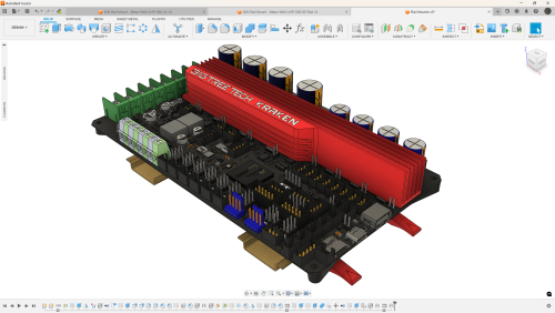
A DIN Rail Mount for a BigTreeTech KRAKEN Controller Board that attaches across two DIN Rails. Print Instructions: The Board Mounting Part is a MultiColor Part for those that fancy it. I've used the usual Voron 0.2mm Layer Height, 4x Perimeter, 5x Top / Bottom Layers, and 40% Infill Settings which should work for anything using Heat Set Inserts. Some parts of the Model come with in the Slicer added Mouse Ears to help with bed Adhesion - If you don't need them just remove the “Generic-Disk” BOM: 4x Voron Style M3x4mm Heat Set Inserts 4x M3x8mm Flat Hat Cap Screws 4x M3.5x8mm Self Tapping Button Head Screws Assembly: Add 2x Voron Style M3x4mm Heat Set Inserts per Rail Mount ( marked in blue ). Use 4x M3x8mm Flat Hat Cap Screws to attach the Board Mount to the Rail Mounts ( marked in blue ). Use 4x M3.5x8mm Self Tapping Button Head Screws to secure the BTT KRAKEN to the Board Mount. Attach the Assembly to the DIN Rails with a sliding motion while pressing down at the end with the Securing Latches ( BTT KRAKEN removed for better visibility ). To remove the Assembly, pull the Latches slightly up followed by sliding it back out. Word of Caution: This Design requires the distance between the DIN-Rails to be of proper length! Too far apart and the rear Hook will prevent the Locking Mechanism from properly seating onto the front Rail. Too close together and the rear Hook might not catch. As such perhaps consider using the Mounts themselves with setting up the required distance between the DIN-Rails.-
- 4
-

-
- bigtreetech
- kraken
- (and 1 more)
-
Version 1.0.0
22 downloads
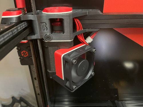
A Mount for installing a 5015 FAN ( like a SUNON MF50152V2-1000U-A99 ) with 40mm Hole Spacing to a 60mm Stepper Motor ( like the LDO-42STH60-3004MAC (S40) ) I tried using Double Sided Tapes and Magnets but neither of them were a reliable Solution so here's a Version that securely mounts it to the Stepper Motor without using the Stepper Motor Screws. BOM ( for a Set of two ) : 8x M3x4mm Voron Style Heat Set Inserts 8x M3x20mm Button Head Cap Screws 4x M3x12mm Button Head Cap Screws Print Instructions: The Parts come as Multi Color Parts for those that fancy it. I've used the usual Voron 0.2mm Layer Height, 4x Perimeter, 5x Top / Bottom Layers, and 40% Infill Settings which should work for anything using Heat Set Inserts. Perhaps use a Brim for the Air Guides since they barely make any contact with the Bed. Installation Instructions: Install two M3x12mm Button Head Cap Screws that will hold the Mount to the Stepper into the Fan Mount - It helps doing this while the Stepper has not yet been installed to gauge how far the Screws will have to be threaded into the Mount. Install the Voron Style M3x4mm Heat Set Inserts into both the Fan Mount and the Air Guides. Use the Fan to Assemble the Air Guides and Fan Mount into a unit using M3x20mm Button Head Cap Screws - Be mindful of a suitable Fan Cable Orientation that works for your Setup. Slide the Fan Mount onto the Stepper with the Screw closest to the Fan catching onto the Stepper Motors Bottom Plate first, then rotate the Mount so that the rear Screw will catch as well. ⚠ Caution ⚠: This was tested with a Chaoticlab CNC Tap V2.0 and no MicroSwitch Endstop Mount attached to it! ( Sensorless Homing! ) This AddOn may not work with any X-Carriers having Parts occupying the space below the X-Axis Extrusion as the FANs now partially do!