Leaderboard


Popular Content
Showing content with the highest reputation since 04/11/2025 in all areas
-
Bodean here from North Carolina! No I'm not a Duke fan or Tarheel fan, lol. I'm retired and I just started this hobby about two months ago. I have a MK4, P1S, SV08, and a Centari Carbon on the way. Also currently trying to decide if I'm building a Trident or 2.4 or maybe both then a zero. Definitely looking forward to the build though. Appreciate this site and the whole Voron community, makes things much less complicated.3 points
-
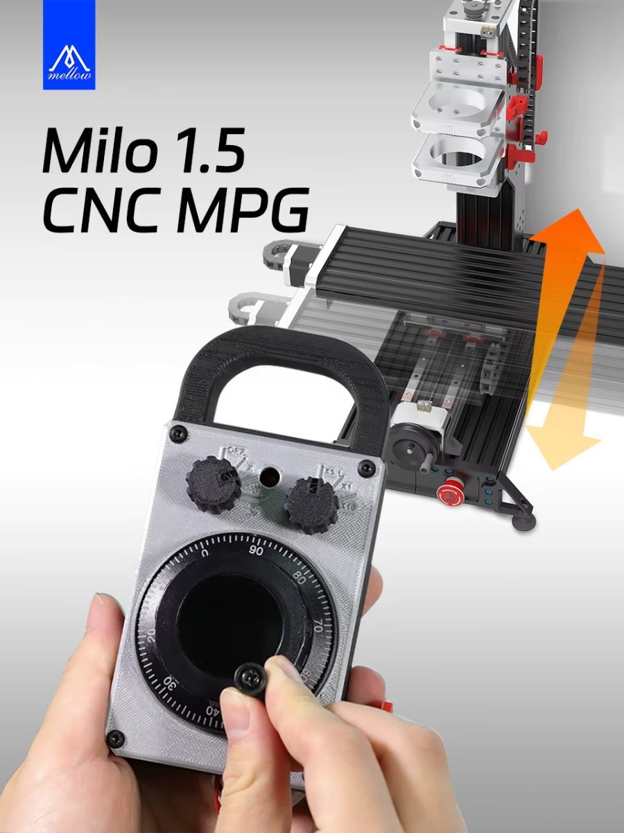
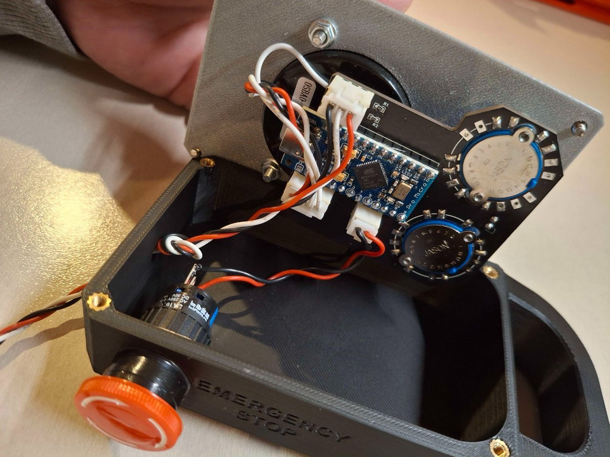
Mellow has assembled a pendant for the Millennium Machine, Milo V1.5 works with the Fly CDYV3 and the BTT Scylla motherboards. Milo Pendant They've done a nice job of making a single circuit board from all the components needed in this mod and flashed the Arduino with the pendant software. I will change the cabling to the Scylla motherboard and add a strain relief to the pendant case. They could have made a better effort in that aspect. I'll also confirm the wiring to the Scylla I/O connector when I receive the pendant.
 3 points
 -
Yup, that sounds about right for the Voron. I'll try squeezing another K or two out over the weekened. Thanks. That's been my experience as well. I experimented with the wall printing order in Orca Slicer. While not perfect I did get better prints overall using Inner/Outer/Inner over the default Inner/Outer. In the past, I never paid too much attention to overhangs because they were generally OK-ish or good enough and got the job done. Now I want a bit more surface quality. So, Rabbit Hole it is... I'll give the Torture Egg a try and see if I can get some improvement.3 points
-
Welcome. As @claudermilk hinted - you're hooked. (Well we have that in common) I started with the Reality clan (Ender3, Ender5 and Ender 5 Plus) Then wanted muticolor printing and got a CRX (dual extruder, single hottend) Read about CoreXY printers and decided I want one. Not knowing much - I went out and bought a TronXy 5XA. Modded the printers to the extreme but decided I still did not have a true COREXY. The Voron journey started. Looked at the BOM, could not decide what to build and self sourced parts for a V2.4, Trident, Switchwire and a V0.1. Needless to say - built them all. Then I decided I need to see if ordering a kit is better/cheaper - Along came another V2.4 and Trident, Trizero, Boxzero. And the Tronxy - It is now an all metal VZBOT AWD. Not forgetting the desire for multicolour - started down that rabitthole and it soon became a deep burrow. ERCF v1, ERCF Community addition (x2), Tradrack (x2), Self sourced Box Turtle and just completed a LDO kit Box turtle. Getting the gist of "escalated quickly"? But it was all very enjoyable and satisfactorily and I hope your journey will be too. Welcome again, and please consider a build diary for your projects.2 points
-
Welcome to the forum! So...two months into the hobby and you have 4 printers and are thinking about building up to 3 Vorons? Well, that escalated quickly!2 points
-
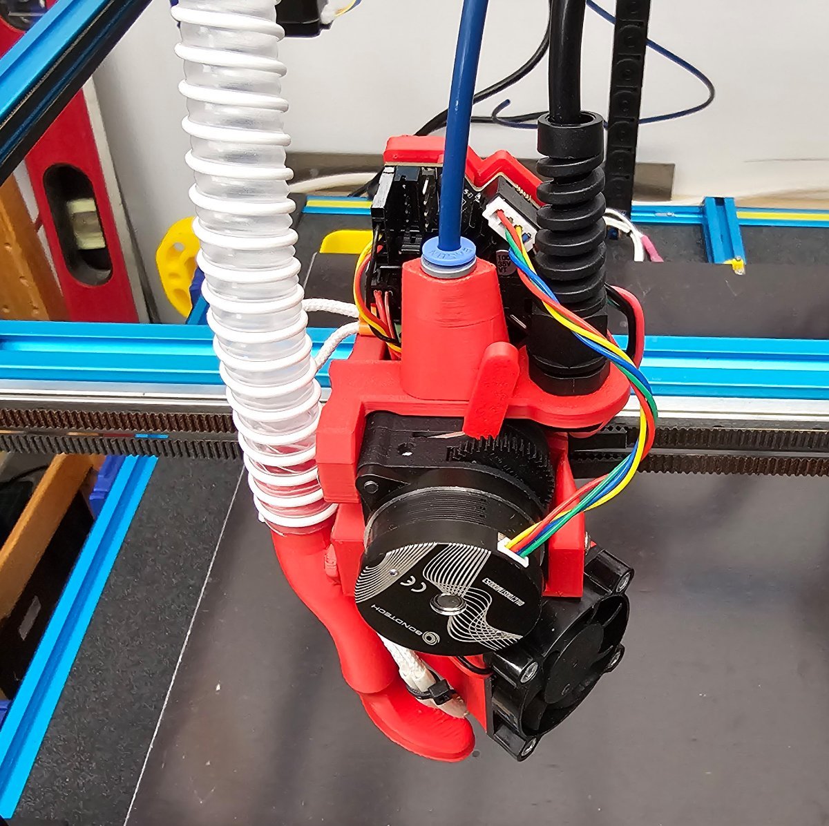
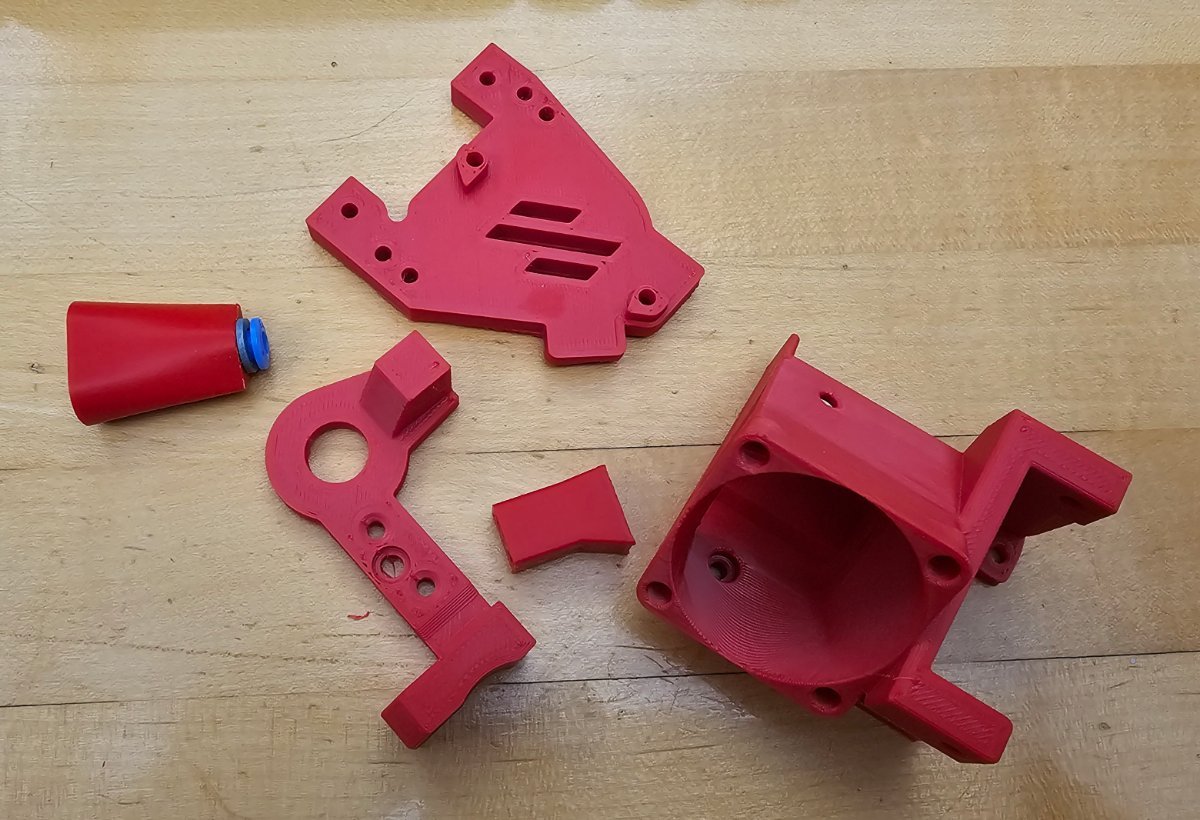
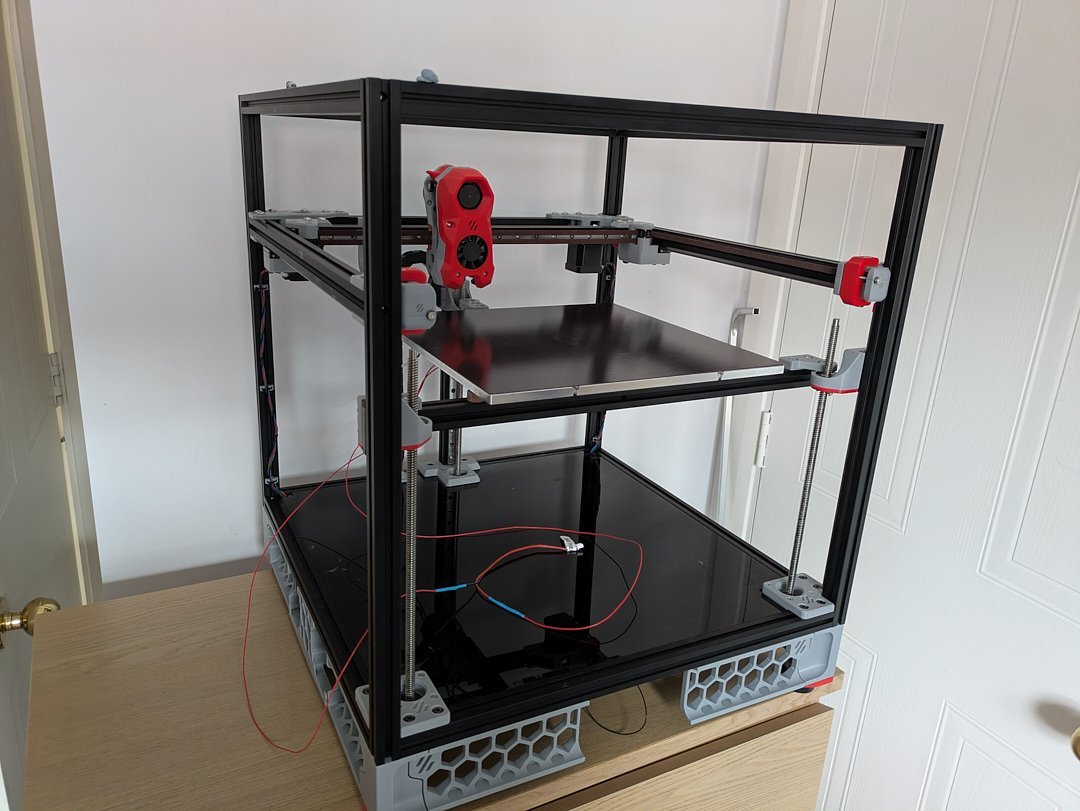
Update! All printed parts for the head (minus the ECAS of course!): On the printer: ...and from underneath: Need to wire the CAN cable to the U2C, CPAP motor and 1st run soon.
2 points
-
I would give Hector at Fabreeko a call. He has a large format laser and can cut custom panels. Printed Solid also makes custom panels but they need a DXF file from you. TBH, making the panels yourself isn't any harder than cutting a piece of plywood, drilling a hole or two and cutting out a few notches.2 points
-
Thanks for the in site on the materials. I looked into the kits but since my printer is going to be a 500mm x 500mm x 500mm print area it falls outside of the panel kits offered for the standard Voron sizes. Also so far it has been sourcing the parts and starting basic prints for the Reaper Toolhead. Ill start a build diary once I start the build which shouldn't be to hateful since i am using the Chaotic CNC Bracket kit.2 points
-
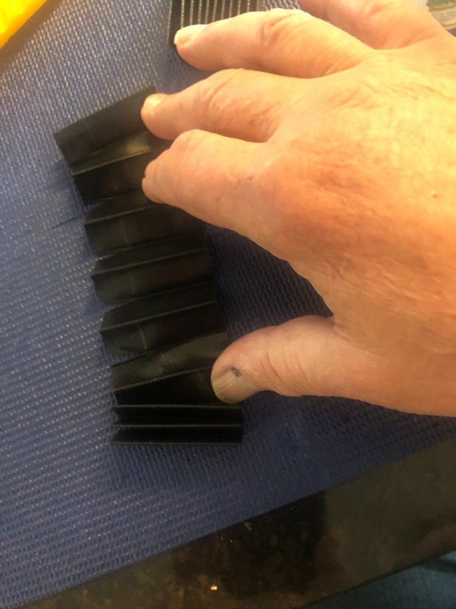
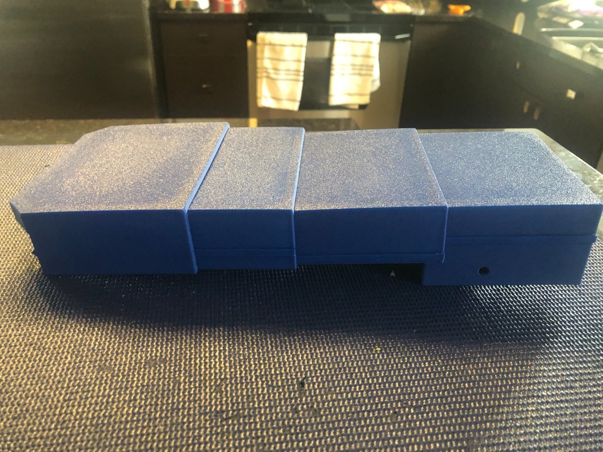
Built the rear bellows from this Discord member Discord Bellows Link . I've uploaded the modified STL and Step files Bellow2 - with holes v1.stepBellow2 v1.stepBellow2 - with holes v1.stlBellow2 v1.stl Make the side bellows so it fits between the V of the top bellow. Shown is the slit of the side below. The side bellows installed. I'm looking at modifying the Y-axis transition bracket to fit the rear bellows The bad news in order to secure the rear bellows to the X/Y carrier is the X axis assembly needs to be removed. You need to remove the toolsetter, remove the hand wheel, remove the leadscrew lock sleeve, disconnect the X stepper wiring, remove the X stepper motor and loosen the grub screw of the stepper to TR8 bushing, pull the stepper of the TR8 lead screw, remove x axis end stop, remove screws from the X axis drag chain end link. Remove the X axis bearing block fromt he extrusion, pull the X axis extrusion assembly of the linear bearings, install linear bearing dummy rails.
2 points
-
Here is a link to program the VFD2 points
-
Firstly... Welcome Secondly... West3D has panel kits ready to go. You'll need two panel kits. Get ACM panels for the rear, deck plate and bottom. I say this because my acrylic deck plate taco'd from heat. From experience I would rate deck plate material as follows... ACM=Best, ABS=Good, Acrylic=Poor Get clear acrylic panels for the top and sides. Since you're in the middle of building or getting ready to build... consider a clicky-clacky door kit as well. If West3D doesn't have what you need Fabreeko is also a good choice. Creating a build diary and posting your progress is highly recommended not only as a way to document your journey but it's also a great platform to post problems that the team members can help you with and others that experience the same issue can benefit from your experience. So, good luck on the build2 points
-
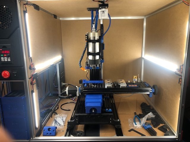
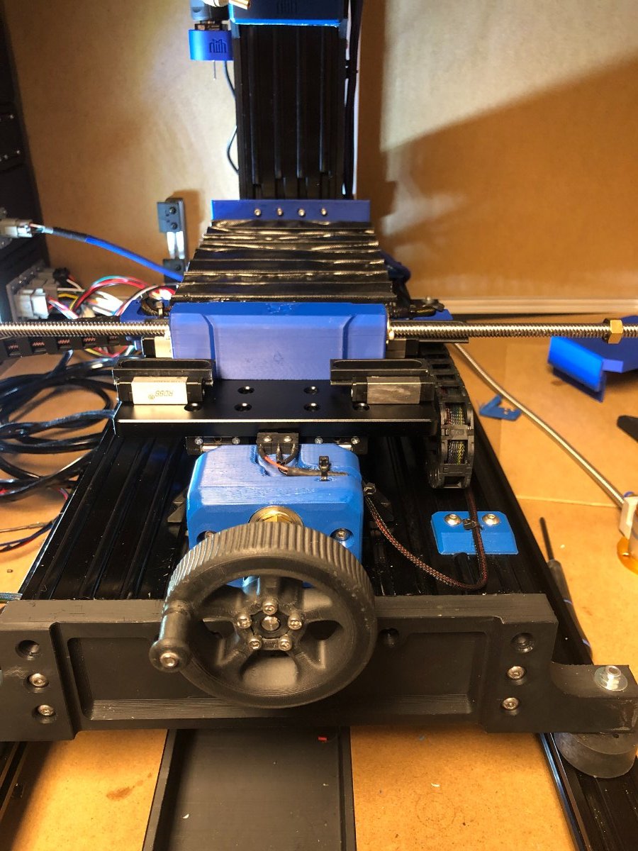
I've been building this project for a long time, and a few followers and I have been anxious to see the mill make some chips! I didn't want to start cutting without having an Y-axis bellow solution to keep chips out of the leadscrew area. I found two types of bellows from two different Discord members, one for the front bellows and the other for the rear one. The front bellows are 3D printed parts a nice feature is it fits over the existing Y axis bearing block and the Y end stop switch is now covers to eliminate any chips reaching it. You’ll also need to tweak the endstop lever bend it toward the Z tower about 1/8”. Front Bellows Bellow Milo.mp4 Still working on the mounting of the rear bellows. I've also installed 24V LEDs in the Mill compartment and electronic bay.
2 points
-
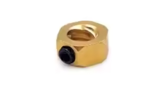
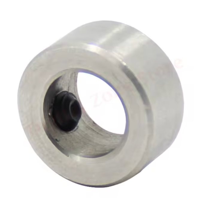
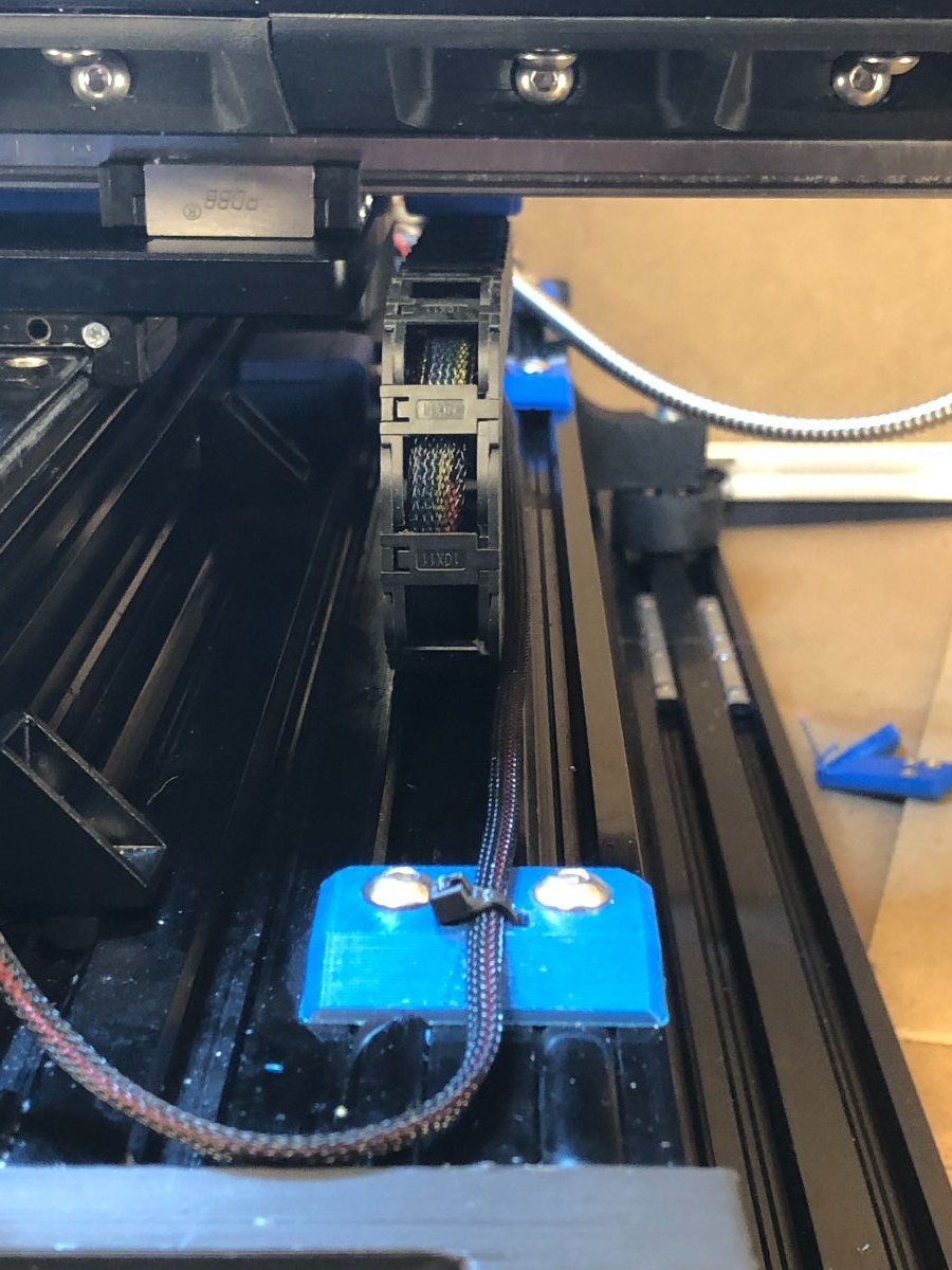
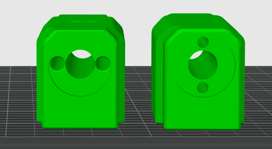
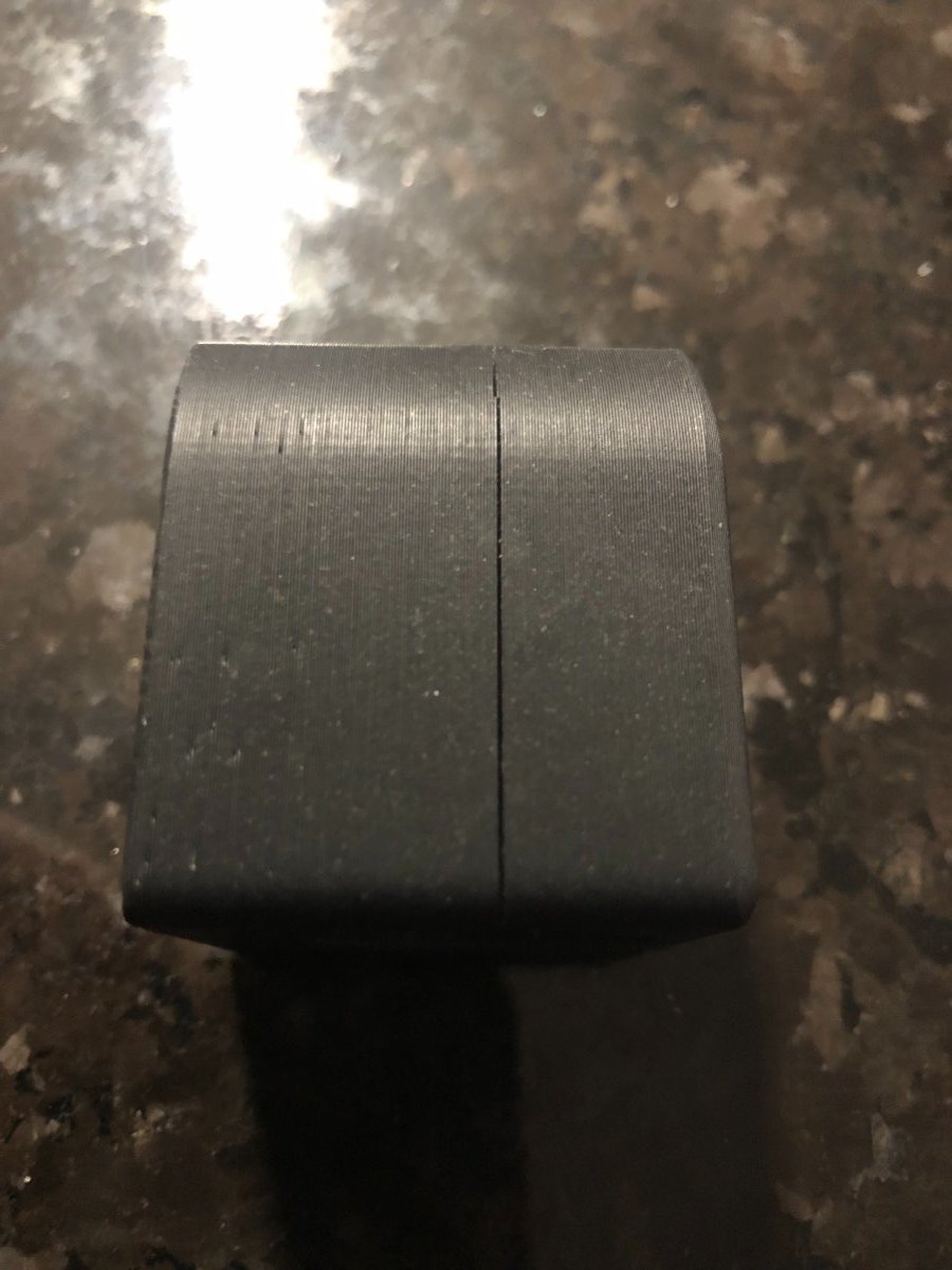
@Penatr8tor @mvdveer I'd suggest getting these leadscrew nuts. These ensure the the grub screw seat on the thread of the leadscrew. The conventional lock sleeve has the potential of seating in between (the void) the leadscrew threads @mvdveer Installing these on the X/Y is not too bad on an assembled mill. Pull the handwheels off, remove the TR8 lock sleeve, and unbolt the stepper motor from the frame. This allows the axis to move freely and gives you access to the rear TR8 lock sleeve. TR8 Leadscrew Locknut
2 points
-
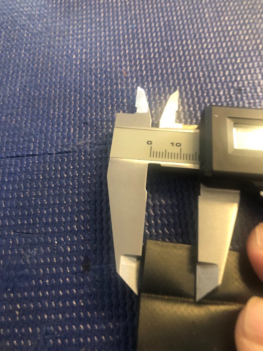
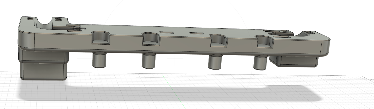
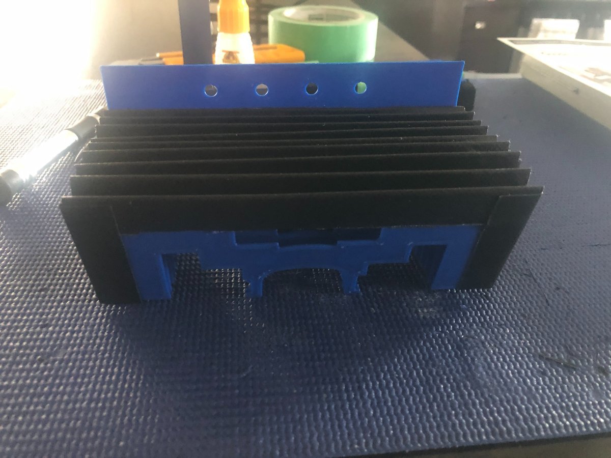
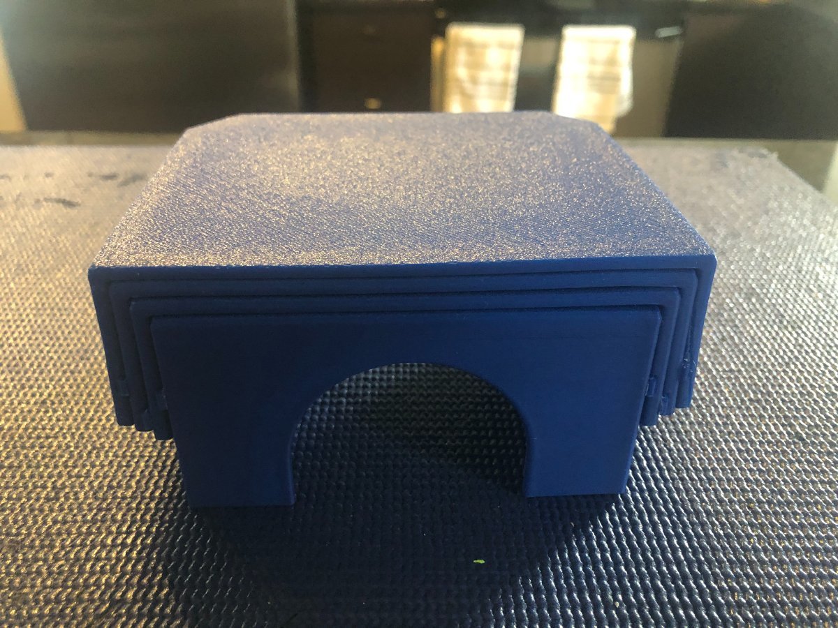
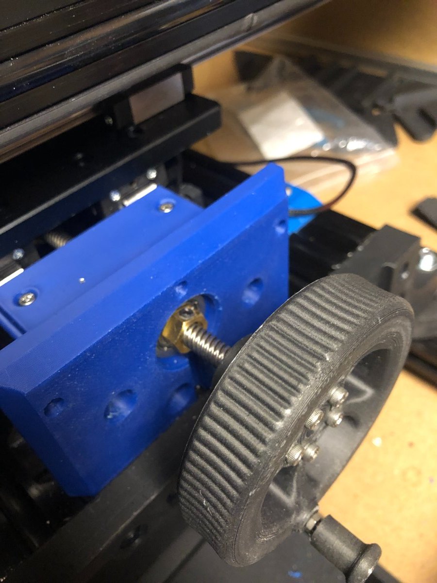
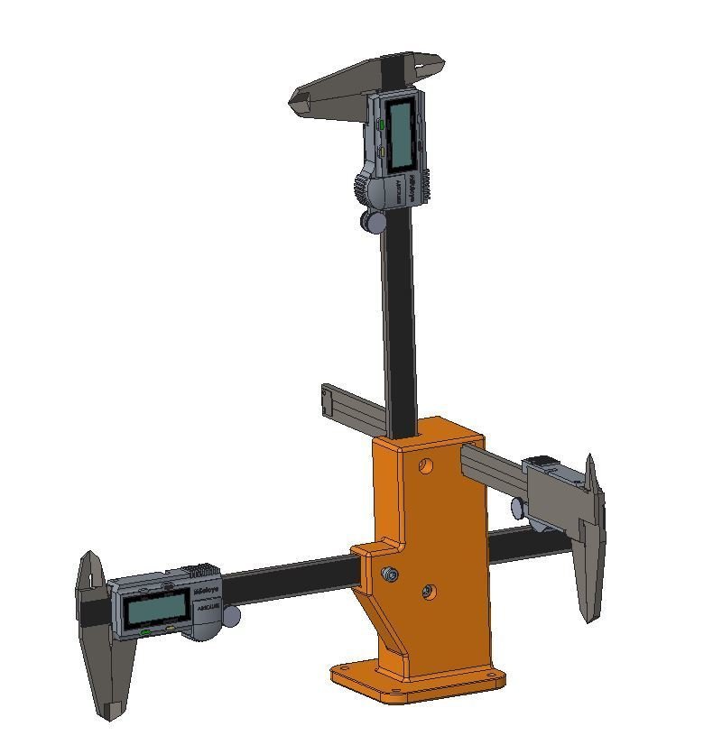
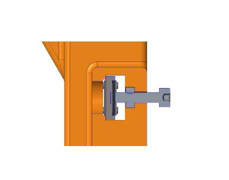
Found this handy tool to calibrate your steps. Use an M4 nut and screw to secure the caliper to the tool. Steps Calibration Tool
2 points
-
Welcome to the forum! If you're building the three Vorons, I'd suggest zero, Trident, then 2.4.1 point
-
I thought I might as well pop a thread here as I will have a list of questions to run through on this build. One night, while my wife was out, I had a bit of a browse of ebay and came across an interesting project (as you do) and popped in a cheeky bid not expecting to get it.... and won it. A 'sort of finished but not finished' Tridex. When I picked it up and run a tape across it I realised it was actually a standard Trident 350 frame & rails with a 300mm bed and a bit of a mix in the two toolheads with the bare minimum of panels etc to get it working. I managed to get some data off the klipper install and she had a total of 10 printing hours - i.e the setup phase. Looking further into it I realised the prints were delaminating so decided it needed a full reprint ... but on investigating the Tridex documentation it looked like a 300mm bed was still a bit big on this size frame and it was going to take quite a bit to get it to the standard tridex specification ...... .... so a conversion back to a standard trident was the best course for what I wanted .....a standard trident 350mm with a 300mm bed. The bonus is I still have the Tridex steppers so I can head back down that path with an appropriate frame later on if I want multi-material rather then multi-colour.
1 point
-
Set this in the Z-Tilt section. Change this value to 15 for example horizontal_move_z: 10 I am a bit biased - All my printers have Mellow boards. As they all have Stealthburner toolhead, I use the SB2040 boards. For those printers without Stealthburner, I use the SHT36 from Mellow. Have not had a problem (13 printers with Mellow boards) You can do an internal spool on a standard Trident 300 - mine has this. So that won't be a problem1 point
-
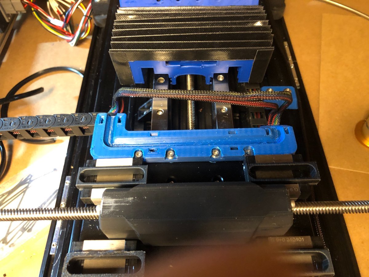
The X/Y axis was reassembled, and the rear bellows were installed. The drag chain bracket mod worked out pretty well to realign the drag chain with the extended transition bracket. img_2919.mp4
1 point
-
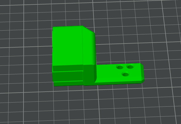
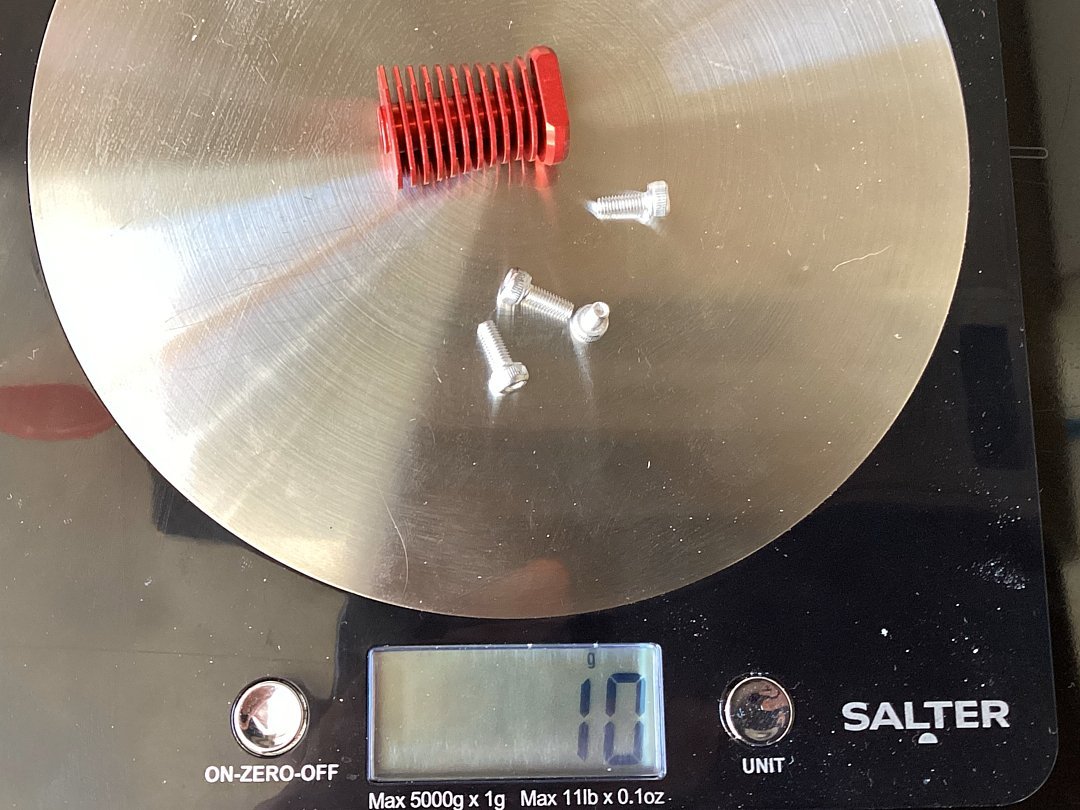
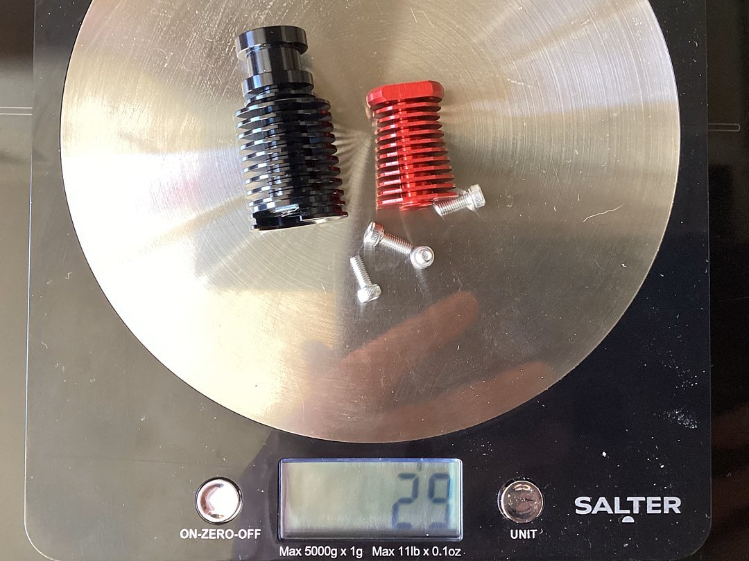
Weight with 4 x M3x8 stainless screws and it pops it up to 10g. Photo side by side with the V6 revo. All pretty academic in my case as not pushing large accel numbers but support for the V6 style in some of the more boutique toolheads is not there thus the move to the Revo Voron to see what I can build to improve my accelerations on a 350mm size frame without moving to a different ecosystem.
1 point
-
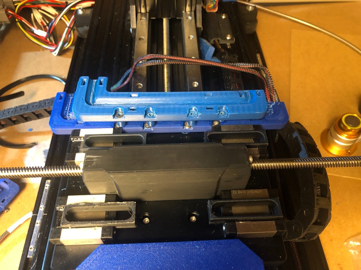
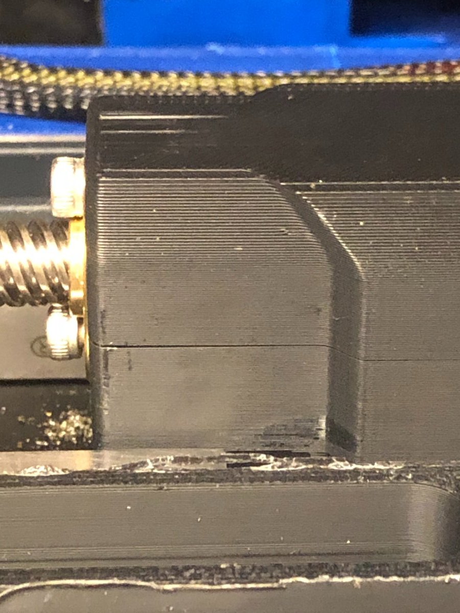
I removed the X-axis to measure what I need to extend the cable transition bracket so the bellows fit against it. Transition bracket extended comparison. Extended the Y cable chain mount by 20mm so it lines up with the extended cable transition bracket. Glad I took it apart, the X anti-backlash block had a crack in it. I'd printed the LDO X Anti-Backlash Nut. When they added more material, they moved the M3 heat insert hole from top and bottom to side to side and re-tweaked the hole size, which prevents the heat insert from bulging the plastic into the hole where the TR8 nut goes. Turned out the Y anti-backlash nut was cracked as well. X Axis Anti Backlash Nut x1_LDO.stl Y Axis Anti Backlash Nut x1_LDO.stl
1 point
-
Best as I read that error log, you have not upgraded the firmware in the Orbiter Toolboard. It's at v0.12.0-166, and your current Klipper system is at v0.12.0-4851 point
-
@PFarm I checked out the bellows thread. It looks like a really cool mod. Definitely something I'm going to add to mine. The clear blue MXD U-Fold Sherline bellows are very interesting. I think this is something that could potentially be adapted to the Milo. What I like about it is that it's all one piece.1 point
-
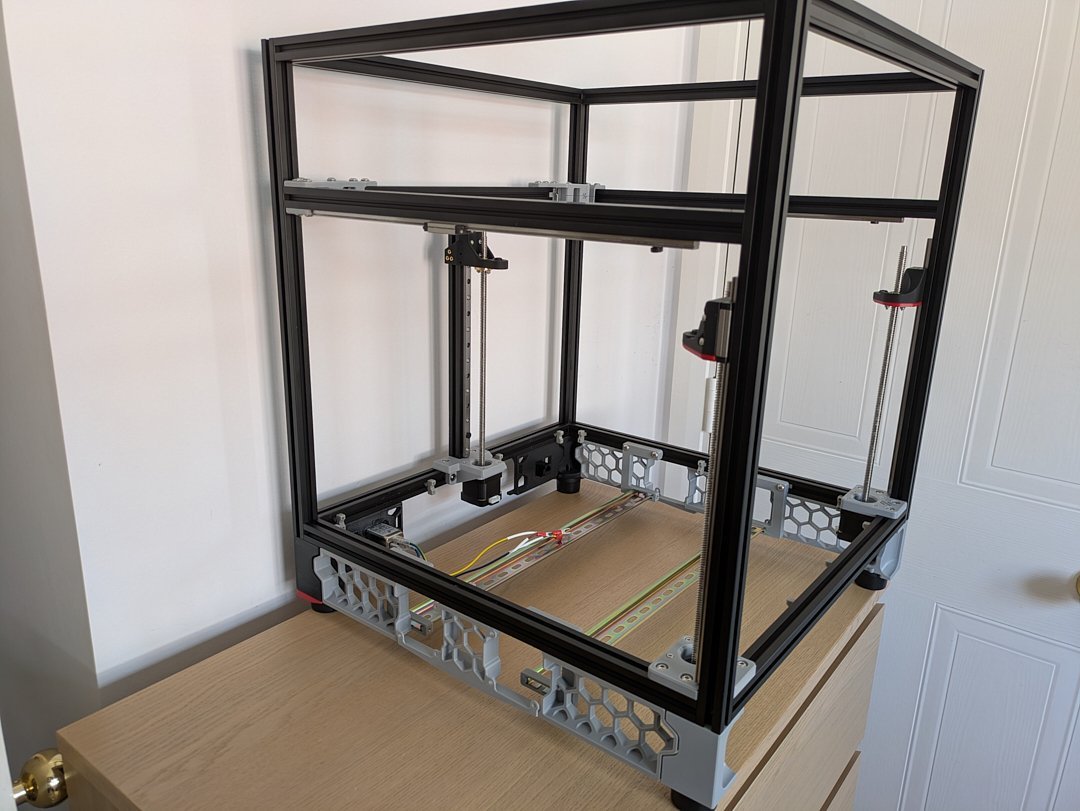
Hi I am building my first Voron 2.4 style large format printer. My current conundrum is sourcing the acrylic for the panels. I was thinking about printing the panels in pieces and finding a way to secure them to each other that makes it appear like one smooth piece.1 point
-
I went through all the VFD settings and got them all set to the suggested settings. Now the spindle comes on when I turn the machine on from the main switch but I still cant control it from the console. Going to go over wiring and settings again but not sure what is wrong. Hoping for some insight. rout and aout were swapped. spindle is working now Also had to program VFD which was not included in LDO setup. Thank you @PFarm for the documentation1 point
-
Thank you for the help!1 point
-
Stumbled across an answer of sorts on the Fabreeko discord. Apparently quite a few people have issues with the Nitehawk and this fan. (4-wire version.) One guy sets his his with "hardware_pwm: true", and "cycle_time: 00004 # 24kHz". Tried those settings, and it runs much better; still a bit rpm heavy at the low end; 2% is as low as it goes, and it's making noise at that (not the quietest fan going....) It's not ideal, but it's useable at this point. I can fine-tune it as I go - - at least I can print with it now!1 point
-
I agree with your point of view. You have pointed out the key issues and it is very instructive and helpful.1 point
-
The 300 mm with the updated Stealthburner is running ~200 mm/s @6K. My current problem is cooling and can be seen clearly on prints with overhangs that start looking bad after a few perimeters only on the back side of the printed object. Placing the object 90 degrees from the previous location will print that overhangs with better results. For example, for the Maker's Muse Torture Egg, I need to slow down the print job down to 45% speed to get good overhangs at the very bottom and top sections. The rest prints great at full speed.1 point
-
Music to my ears - there are other like me, Im no longer alone. Hey wifey - come read this!1 point
-
Keri, when I tried first "defining" the PT1000 with three resistance/temp values, then declaring that defined thermistor in the configuration, it gave Klipper a fit. Wasn't until I got rid of the definition and declaration, and simply stuck "PT1000" in sensor_type and 2200 for pullup resistor, exactly as midmadn said, that things started working better. Apparently when you try to tell Klipper something it already knows, it gets testy! I can see how that jumper works - - slick way to implement different resistor values for different thermistors! I don't think such strict accuracy is required for quality prints; likely using a PT1000 for printing with plastics is overkill, like using a shotgun to deal with mosquitoes, given that printing temp ranges stated for any given filament are closer to ballpark estimates than to three decimal-place precision figures. I'll forget about the precision and just take advantage of the greater range. Yeah.... this is exactly the kind of rabbit-hole I'm far too prone to get sucked into! I get caught up in the technical side of it and forget about the 'diminishing returns' aspect. It's great fun when you finally figure things out and everything works, but if it makes no practical difference in the end, it's just for fun (or "funstration," as my partner-in-crime likes to call it, given the dearth of accurate and *complete* information.) I think consumer/hobbyist-level 3D printing is still in the "wild-west' stage, much like phonographs were back in the day, when each manufacturer did their own thing, records played at different speeds for different makers, etc - - took quite some time for any industry-wide standards to become established. Still, this printer is serving it's purpose; I spent three decades learning to troubleshoot and repair some fairly complex equipment, and hated the thought of losing those hard-won skills in retirement. For me it's more about tinkering with the technology than actually printing useable and/or fun stuff.1 point
-
Excellent writeup @ChicagoKeri1 point
-
OK, weight results are in... and inconclusive! A Stealthburner X Carriage with all brass inserts installed: Generic ABS , 36 grams Fiberon PPS-CF10, 33 grams A Stealthburner Revo printhead with all brass inserts installed: Generic ABS, 48 grams Fiberon PPS-CF10, 54 grams There was apparently some difference in print settings in the otherwise identical parts. So as a whole, I'd call it a wash. It's probably not worth the effort to reprint the ABS ones with more up-to-date settings, and certainly not worth the brass inserts. added: A test Orca Cube came out at 30.00mm/ X, 30.08mm/ Y and 30.02mm/ Z. The screw plug is a tight fit but turns all the way in. Surface finish is good if you like the textured look and feel.1 point
-
I'm glad you got it fixed enjoy using your Milo!1 point
-
Yup and you know what... a complex part is just a combination of simple features. Just keep modelling. ...and there's not really any repositories for CNC machined stuff like Thingiverse and Printables, you pretty much have to design you own stuff. I would bet that there might be some clamps or other workpiece holding things you could machine for the Milo to get ya started. Hit me up when... I mean IF you get stuck.1 point
-
If you are going canbus, I would use the X-endstop on the TAP as that eliminates a wire running along the Y-axis cable chain for the X-endstop on the XY pod. Another mod is to eliminate the Y-endstop wire and thus getting rid of this cable chain by mounting the endstop on the AB motor mount. (here is one example) In Summary: 1. Do not use XY endstop pod 2. Mount X-Endstop to the TAP body and wire to the Canbus on the toolhead 3. Mount the Y-enstop on the AB Motor mount (Here is an example of this on Github, or a simple solution on printables) 4. You don't need a Z-endstop - TAP takes over this function I will avoid Hall effect or sensorless homing for the time being - get the machine up and running and if you then want - change. As long as you use good microswitches(Omron), you should not have a problem. Hope it clarifies it for you1 point
-
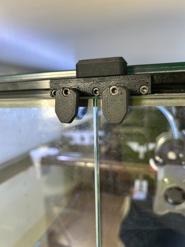
Version 1.0.0
221 downloads
I wanted a more accessible door-closing mechanism for my glass doors, which provides some pressure to seal the door. It uses a simple half-helix. You might have to amend the height for your specific panel thickness.1 point