Leaderboard


Popular Content
Showing content with the highest reputation since 08/27/2021 in all areas
-

Version 1.0.0
631 downloads
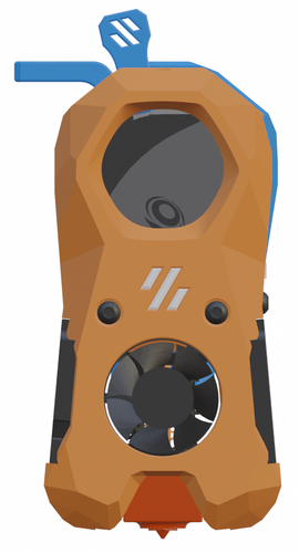
I was having trouble getting my enclosure temperatures above 45C to achieve my optimum print settings. This is the solution I came up with to solve my enclosure temperature issues. I'm running a Fystec Spider v1.1, so your printer config would likely differ. I'm also using a Hartk v4.0 PCB that has an integrated chamber thermistor. I've included my settings for this as well, but you may need to change this up if you use a different thermistor for enclosure temperature readings. I hope this is helpful for someone. I couldn't find a lot of solutions out on the net that could get me up and going with a setup like this, so it was a lot of trial and error to get to this point. Let me know if you have any comments or suggestions that can help me make this thing better! How I set things up: I removed the fan from the PTC heater and inserted a 100K NTC thermistor into one of the bordering fins on the heater core. I then filled the remaining gap in the fin with thermal grease and reattached the fan. I added a thermal fuse to make sure the power would get cut if the temperatures get out of hand from a bad config or faulty piece of hardware. First I drilled a 1/8" hole next to the center ground pin, rivetted the fuse to the heater's core, and applied thermal grease between the fuse body and the heater core. I then moved the ground wire to run from the fuse rather than the tab. Once I wired this up, I ran the temperatures up past the fuse limits to verify things fail safely as expected. I then replaced the fuse after test failed as expected. I extended all of the wiring with solder connections to make sure it would be long enough reach each wire's intended destination, and capped each connection with heat shrink. I mounted the PTC heater to the printed PTC heater mount and ran the wires to the wiring compartment. I installed the Omron relay, and ran a 24v output from my controller to the relay's 5-24v input. I then routed 110v AC to the other end of the relay on the hot lead. I finished up the wiring by hooking up the 12v line for the heater fan and the heater thermistor to the controller board. (Note: my chamber thermistor was already installed on my toolhead's PCB) I updated my printer.cfg and ran a bunch of tests on the heater to make sure it was functioning properly. BOM: Electronics: - PTC Heater w/ Fan x1 - Item on Amazon - NTC 100k thermistor - Item on Amazon - 120C Thermal Fuse - Item on Amazon - Omron 5-24v Relay - Item on West3D Printed Parts: - Printed PTC Heater Mount x1 Miscellaneous: - M3x8mm SHCS x2 - M3 T-nut x2 - 18awg stranded wire ~2 meters - 22awg stranded wire ~2 meters - 1/8" Rivet x1 - Appropriate connectors for you controller board Changes to printer.cfg: ###################### ### Chamber Heater ### ###################### [heater_generic chamber_heater] heater_pin: PC8 sensor_type: Generic 3950 sensor_pin: PC2 control: watermark max_power: .5 min_temp: 0 max_temp: 110 [verify_heater chamber_heater] max_error: 120 check_gain_time: 120 hysteresis: 5 heating_gain: 2 ########################## ### Chamber Heater Fan ### ########################## [heater_fan chamber_heater_fan] pin: PB6 max_power: 1.0 heater: chamber_heater heater_temp: 40.0 # fan will turn off below this level ############################# ### Enclosure Temperature ### ############################# [thermistor chamber_thermistor] temperature1: 25 resistance1: 10000 beta: 3950 [temperature_sensor enclosure_temp] sensor_type: chamber_thermistor sensor_pin: PC1 min_temp: 0 max_temp: 80 Macro: You can run this and immediately start your print. The print wont actually start until the specified chamber temperatures are reached. [gcode_macro CHAMBER_TEMP_WAIT] gcode: {% if params.MIN_TEMPERATURE and params.MAX_TEMPERATURE and params.MIN_TEMPERATURE|float > params.MAX_TEMPERATURE|float %} {action_raise_error("Chamber Temp Wait: MIN_TEMPERATURE must be less than or equal to MAX_TEMPERATURE Use: - CHAMBER_TEMP_WAIT MIN_TEMPERATURE=[0..80] - CHAMBER_TEMP_WAIT MAX_TEMPERATURE=[0..80] - CHAMBER_TEMP_WAIT MIN_TEMPERATURE=[0..80] MAX_TEMPERATURE=[0..80]")} {% elif params.MIN_TEMPERATURE and params.MIN_TEMPERATURE|float > -1 and params.MIN_TEMPERATURE|float < 81 %} {% if params.MAX_TEMPERATURE and params.MAX_TEMPERATURE|float > -1 and params.MAX_TEMPERATURE|float < 81 %} TEMPERATURE_WAIT SENSOR="temperature_sensor enclosure_temp" MINIMUM={params.MIN_TEMPERATURE|float} MAXIMUM={params.MAX_TEMPERATURE|float} {% else %} TEMPERATURE_WAIT SENSOR="temperature_sensor enclosure_temp" MINIMUM={params.MIN_TEMPERATURE|float} {% endif %} {% elif params.MAX_TEMPERATURE and params.MAX_TEMPERATURE|float > -1 and params.MAX_TEMPERATURE|float < 81 %} TEMPERATURE_WAIT SENSOR="temperature_sensor enclosure_temp" MAXIMUM={params.MAX_TEMPERATURE|float} {% else %} {action_raise_error("Chamber Temp Wait: invalid usage Use: - CHAMBER_TEMP_WAIT MIN_TEMPERATURE=[0..80] - CHAMBER_TEMP_WAIT MAX_TEMPERATURE=[0..80] - CHAMBER_TEMP_WAIT MIN_TEMPERATURE=[0..80] MAX_TEMPERATURE=[0..80]")} {% endif %} Updates: - I added a photo of how this is wired up in the wiring compartment. The boxes with the text in the photo represent the components of the heater that are in the chamber of the printer. - I have included the macro to wait for chamber to reach temps before starting a print. - I have attached the heater mount's fusion 360 file for others to be able to easily make edits to the chamber heater mount Chamber Heater Mount v2.f3d40 points -
Version 2022.05.21
3,863 downloads
RockNRoll - Rockers for Voron V2.4 This mod is intended to make access to the electronics compartment easier by enabling the printer to be rolled on its back without damaging cables or the exhaust system. The rockers are mounted on the vertical extrusions in the back replacing the panel corners. Additionally they are braced against the horizontal back extrusion. The mod is designed for and tested with a 350mm V2.4, but it might work with a V1 or Trident as well. Due to their higher center of gravity V1 and Trident might need additional feet higher up. If you tried this mod on a V1 or trident, let me know how it went on discord. Gallery: To give you an example how this works, take a look at these pictures: Hardware needed: pcs. name 4 M5x10 BHCS 4 M3x12 SHCS 2 M3x20 SHCS 4 M5 T-nut 4 M3 T-nut 2 M3 Threaded Insert As all these are in the BOM of a V2.4 it is highly likely you can build this mod with leftovers from your printer. Printing: Parts: To start off you need to print these parts: 1x rocker_right 1x rocker_left 1x rocker_right_brace 1x rocker_left_brace If you use thicker panels or foam tape than the default 4mm, there is a 6mm version in a subfolder. For additional support you can swap the base plates of the rubber feet to the ones from this mod. If you are building a 2.4r2 print these: 1x base_plate_a_r2 1x base_plate_b_r2 If you still have an 2.4r1 build you therefor need: 1x base_plate_right_r1 1x base_plate_left_r1 Print Settings: This mod needs rigidity and stiffness. Based on the Voron recommendations for structural printer parts these settings are recommended: 0.4mm Nozzle 5 Perimeters 40% Infill 10 top and bottom Layers The test prints in the pictures are done with Formfutura rTitan ABS. Support: All the STLs are oriented correctly. The rockers themselves have overhangs where the backpanel is supposed to sit. Don't forget to remove the three support tabs integrated into the 3D model before mounting: Assembly: Threaded Inserts: Start with melting the M3 threaded inserts into the braces: Mounting the Braces: Remove the bottom corner panel clips of the back panel and insert the T-nuts. Put two M5 T-nuts into each vertical extrusion and two M3 T-nuts on each side of the horizontal extrusion. Put the braces roughly in place and screw them in lightly with two M3x12 SHCS bolts each. Mounting the Rockers: Make sure the T-nuts line up with the holes in the rockers and mount the rockers on their braces. They should slot right in. Bolt rocker and brace together with a M3x20 SHCS bolt before mounting the rocker on the vertical extrusion with two M5x10 BHCS bolts. Once every bolt is in place, tighten them all up. Optional: Mounting the Base Plates: To increase the support of the rockers you can swap out two of the original base plates of the rubber feet with the ones of this mod. They slot into the rockers tip and support it while tilting. There are STLs available for both 2.4r1 and 2.4r2. The mounting example shows the r1 version, mounting the r2 version is similar. Start with playing your favorite Elvis song and rocking and rolling the printer on its back for the first time. Remove the rubber feet and the stock base plates: Swap the M5 nut of the stock base plate to the new one and slot the fork tips of the new base plate into the rocker. Then screw everything back together:39 points -
Version 1.2.5
47,134 downloads
The Mini Stealth v2 toolhead is up on GitHub now. I will keep these files here as the new parts are not compatible with the v1.2.5 parts. I will support both versions in the comments here. I still need to create new assembly instructions but a lot of the steps are similar to what is described here. --------------------------------------------------------------------------- This toolhead scales down the body of the Stealthburner to a size which fits into a V0.1/V0.2. Fully assembled it weighs about 110 grams less than the original. It is designed around the Orbiter 2.0 extruder and has versions for the Phaetus Dragonfly, Dragon and Rapido HF hotends as well as versions for the Mosquito, the Revo Voron and the Creality Spider Pro hotends. It incorporates a status LED as well as two for print visibility. I have added new stretched versions that should fit the Rapido UHF, Dragon UHF and the VolcoMosq hotends. The Dragon UHF and Rapido UHF hotends can fit in the same shroud. The UHF hotends will reduce Z travel by 8.5mm and the VolcoMosq by 3mm. I cannot verify the fitment so if there are any issues please leave a comment. There are now two hex pattern inlays based on the design by 3DP-MAMSIH and a tutorial on how to apply them to the shroud. The negative body feature of Prusa/Super Slicer can also be used to create a crop-top version of the shroud as described at the end of the tutorial. The Mini Stealth uses a pair of 4010 blowers which produce more airflow than a 5015 blower while being notably less noisy and drawing less current. The depth of these fans do limit Y travel by 3mm on a V0.1 while the door is closed and tophat is on. The width of the main body at its base is also a very tight fit at the extremes of X travel. I have raised my tophat by 20mm which gives the cabling and filament tube plenty of room to breathe. The shroud fits a 3010 hotend fan or a 3007 fan by using a clip-in adapter. This Orbiter 2.0 Mini Stealth is a better fit than the Orbiter 1.5 Mini Stealth in a V2.4 or Trident as the motor no longer interferes with the path of the cable chain. There is a separate 'strain_relief' stl for use in the V0.1. There are also x-frame pieces that allow this Mini Stealth to be installed on a Switchwire. The nozzle is moved up by 3mm compared to the official Switchwire due to the stepper motor being so low on the Orbiter extruder but this also allows a BL-Touch to fit into the x-frame pieces. I have included a magnet mount and additional shroud .stl files to make this compatible with the ZeroClick mod. This toolhead also has versions that allow mounting a differential IR sensor. I have removed the mechanical Z endstop on my V0.1 and use the IR probe as an endstop and it has greatly simplified my homing sequence. There are additional x-frame pieces that allow mounting the Beacon3D probe, Euclid or Biqu MicroProbe for a V2.4, Trident or Switchwire. The included Blender file shows the entire assembly complete with screws and should answer most basic questions. Note on MGN-9 installation: The default 2mm x 10 plastic threading screw is too long for mounting the x-axis endstop. An M2 x 8 does the job fine. For mounting to the linear carriage use four M3 x 6 flat-head screws. Note: The MGN carriage shown is an MGN-9H, not the shorter MGN-9C used in the V0.1 mod. Preparation I recommend using a file to lightly remove any printing artifacts on the mating face of the shroud. Use a small file to smooth out the break-off edges of the LED PCB and make sure the LED pockets are clear of 'droopy bits' All three fans will need the wire retention piece clipped so the wires fit into the shroud channels easier. Differential IR Probe Installation The IR Probe needs to be screwed into place with two M2.5x8 FHCS before installing any of the fans, except with the VolcoMosq or UHF hotends where the probe needs to be glued on with CA glue. The Y-offset for this probe is 4mm in front of the nozzle and the X-offset is 32mm. I strongly recommend removing the 3-pin header and soldering wires directly to the probe PCB. When installed the wires will route out from the back of the IR probe cover to then join with the hotend and fan wires. I have included a cover to allow a connector at the probe but the wire management will be less than ideal.. Assembly Instructions After pressing the status LED diffuser into place, install the right part-cooling fan first by feeding the wires through the small hole at the bottom. Then feed the wires for the status LED and hotend fan through before starting to push the LED carrier into position. Carefully push the status LED carrier as far as it will go and press the fan into position while making sure not to pinch the part-cooling fan wires. Then press the remaining LEDs into their slots. (I measure out 35mm of wire to connect these LEDs together) Here is another view also showing where the hotend fan wires fit. Insert the second part-cooling fan and splice the wires together with the first fan. Install the hotend with at least two M2.5x6 screws (M3x6 for the Revo Voron). The heater cartridge should be installed away from the LEDs to avoid overheating them. (** don't forget the PTFE tube) Pre-assemble the extruder pieces before installing into the shroud. Use two M3x8 BHCS to install the Orbiter 2.0 extruder. It helps to have both screws in the Orbiter before putting it in place. Start the screw by the latch and then the blind screw should be easier to align. Gather all of the wires together with a zip-tie next to the base of the Orbiter latch and then use another zip-tie to secure the wires to the motor-bridge. Leave a little slack in the extruder wires. Install the strain_relief or cable_chain_mount with two M3x6/8 screws and the cable_door with a M3x10/12 screw. Close the cable door with a M3x6 BHCS and screw in the extruder tensioning thumb screw. Use two M3x40 BHCS to secure the toolhead to the x-carriage in a V0.1/V0.2. For installation in a Trident or V2.4 use two M3x50 BHCS. Happy Printing!37 points -
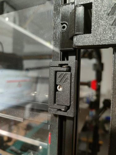
Version 2021.04.03
29,598 downloads
These hinges allow for 270 degrees of motion, from closed 0° to 270° full open parallel with the side panels. This was developed out of an effort of running into tolerance issues with the spec hinges not allowing much room if the two panel doors are used and are slightly cut larger by only 1 mm or so. I ran into issues closing and the doors hitting and needed something that allowed more horizontal movement. So it was decided to figure a way to mount on the side of the printer. After some searching, printing, trial & error, I came to what you see below. 270 degrees wasn't the initial intention but figured if they are going to be mounted to the side, might as well take advantage of the extra flexibility. During development and testing of these I struggled with tape being sufficient with my first version of these. So went back and designed these to use hardware and remove tape from the equation. Hardware mount was heavily influenced by Randell other door hinge mod that uses hardware. The handles in this mod are a remixed version of Randell's to adjust for the altered latch developed for this setup. The latch in the mod gives as much room as possible vertically if panels are slightly too tall. Note: Un-tested but the holes should line up with Randell's hardware for the hinges if you are looking to swap for more swivel. As you can see this setup allows vertical and horizontal freedom if your panels are cut too large. BOM Hinge Hardware M3 x 35 mm SHCS [x4] M3 x 8 mm SHCS [x4] Side Mount M3 x 8 mm BHCS [x8] Backplate. SHCS can also be used here. And if you want a flush look 8 mm FHCS M3 Threaded Insert [x8] M3 T-nuts [x4] hammerhead or spring ball, your choice Latch 3 mm x 6 mm magnets [x4] M3 x 6 mm SHCS [x2] BHCS screws work better here if you have them M3 T-nuts [x2] hammerhead or spring ball, your choice Handles 3 mm x 6 mm magnets [x4] M3 x 6 mm BHCS [x8] M3 Threaded Insert [x8] Printing Use the default recommended for Voron parts. Can be done in PLA but I have not tested this. If having issues printing side mounts you may need to add a brim to those and trim before installation Layer Height : 0.2 mm Extrusion Width : 0.4 mm Infill : 40 % Walls : 4 Solid Top/Bottom : 5 There is a left (a) and right (b), you will need to print 2 for each side. There are 2 versions of each of the hinge faces if you don't want a Voron logo or want to mix and match. Multiple depths are also provided. Should you need a specific depth and no access to Fusion, feel free to reach out to me on discord chrisrgonzales#0731 The 4 mm is typical 3 mm panel and 1 mm foam , and 6 mm files are for 3 mm panel and 3 mm foam. You will need to print 4 of the side mounts, they are not side specific. Assembly These are designed to have a tight tolerance, so the 35 mm screw can be screwed into the lower portion of the face hinge, and still have some play without wiggle. You will likely have to thread it all the way down then play with the hinge and pivot it a couple of times to work it in before attaching. Do not over tighten the screw as it will bind on the upper portion. If you feel it binding, back the screw off just a lil bit. When installing back plates to hinges to protect panel from cracking be careful not to screw down too much as insert depth is shallow as you may risk of pushing through. The backplates have a chamfer for more recessed look, but can be flipped if you have longer hardware. Take it slow when installing heat inserts as it's very easy to push them through and cause deformation on the face of the hinge. Set temp on iron lower than used on most other heat inserted parts as this gives you more time not to press through. Also you may have to use the side of your iron's tip as not to puncture all the way. For placement of drilling, you can install the hinges in place, and tape or use panel clips from sides temporarily to hold front doors and tape outline of hinge. Then remove the panel and hinge, place the hinge where the tape outline is, mark the hole and drill. CAD Files The CAD files are parametric! When opened in Fusion 360, editing the thickness parameter will change the spacing and geometry to allow the hinge full 270 articulation. Enter in thickness of your panel and foam, I would recommend accounting for the compression in your foam. Example 3 mm panel with 3 mm foam, typical 6 mm would be entered, but possible that 5.8 mm might be a better choice to give some compression for a seal. If you are unsure, printing a single bracket and testing fitment and offset would be ideal. If you would like to use this with tape only you may adjust the faceThickness parameter to be thinner but wouldn't suggest going smaller than 3 mm. You will also need to remove or extrude flush the holes for the brass inserts. Also the faceWidth parameter may be adjusted to be smaller width. Would not go lower than 27 mm for this parameter. The logo can be removed if needed. If using Fusion 360 with history, step back two actions and logo will be removed. Otherwise removal of chamfer and extrude flush will be needed. thickness : panel + foam depth in mm (default 4 mm) faceThickness : depth of the face portion of hinge not including panel + foam (default 5 mm) FacePlate_width : width of facing hinge from edge of extrusion to the opposite edge. Not actual width of hinge default (34.9 mm) Taped versions use 27mm. See image below. Questions / Suggestions If you have any questions or suggestions feel free to contact me on Discord chrisrgonzales#073134 points -
Version 2021.12.07
4,657 downloads
Printable quick release latch for panels on 2020 extrusion This is originally inspired by a youtube video - https://www.youtube.com/watch?v=6p7M18oPn3k Another user is creating cad and variants - https://github.com/v6cl/My-Voron2.4-Customs/tree/main/Panel_Locker So why did you do it? I wanted a variant with filament hinges I found it didn't put quite enough pressure on the panel and my attempts to moodify the cad failed Decided the best way to understand it was to design it Wanted adjustable33 points -
Version 1.0.0
1,062 downloads
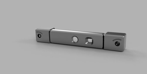
This belt clip is designed for the 9mm Z belt.31 points -
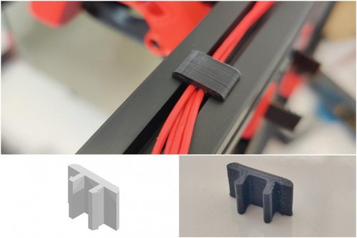
Version 2021.09.01
887 downloads
Misumi Cable Clip Credits: Eddie from the Voron-Team (From his awesome Misumi Led Clips) Printing: Default Voron settings, correct orientation, no supports Bom: Nothing Description: It's a stupid Clip to hide your cables stiff and secure inside that extrusion cutout. You can scale this in Z-Size to whatever you want. By default it's 8mm, as i find it the perfect size. Please don't even try to print only one of this, it's tiny, you need layer-time xD Pictures:28 points -
Version 2021.09.07
6,915 downloads
Longtime Testing Phase! Update (02.09.21): STL's available for testing! Please print and report issues! Update (03.09.21): Added24 points -
Version 1.0.1
3,160 downloads
I really like this spool holder and had to make a Voron 2.4 adapter for it. I didn't want it to interfere with the glass panels, so it's been designed to avoid touching them at all. BOM: Roller Holder Mount x1 Roller Holder x1 Roller x1 Skateboard Bearing x2 (can be substituted with plastic bearings provided as stl files) 3x12mm SHCS x1 3mm T-nut This has been a welcome addition to my printer. Print Settings: Supports: Yes Resolution: 0.2mm Infill: 40-50% Wall Thickness: 1.6mm Here is a link to the original version of this spool holder: https://www.thingiverse.com/thing:3020026 Update: 5/4/2022 Depending on where you mount the spool holder and how you are routing your filament, you may need an extended bowden tube guide. After some questions around this, I have included the STL file for the an extended version of the stock Voron 2.4 bowden tube guide incase you run into this issue.24 points -
Version 2022.02.05
557 downloads
Top Corner Cable Hide/Cover (LED Wires) Designed to hide cables that are running around the top corners of 2.4 extrusions behind the z idlers. They are large enough to fit 3 pin microfit connectors. There maybe some small loss in z. Don't forget to check your clearances after installing. Pro tip: It may take some fiddling to get the wires to fit. You will know they are in place when it sits flush to the extrusions without wobbling. Also disable 'Thin Walls/Detect Thin walls' so the mounting ears print cleanly. Printing Default voron settings No supports needed BOM Size Qty M3x8 8 M3 T-Nut 824 points -
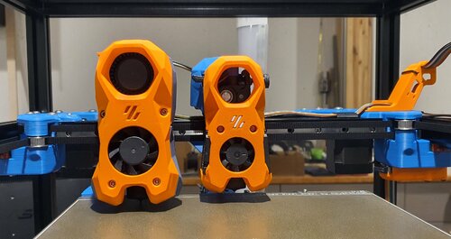
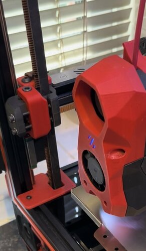
Version 1.2.5
23,039 downloads
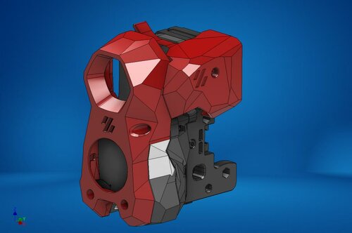
The Mini Stealth v2 toolhead is up on GitHub now. I will keep these files here as the new parts are not compatible with the v1.2.5 parts. I will support both versions in the comments here. I still need to create new assembly instructions but a lot of the steps are similar to what is described here. --------------------------------------------------------------------------- This toolhead scales down the body of the Stealthburner to a size which fits into a V0.1/2. Fully assembled it weighs less than 260 grams. It is designed around the Mini Sherpa extruder and has versions for the Phaetus Dragonfly, Dragon and Rapido HF hotends as well as versions for the Mosquito, the Revo Voron and the Creality Spider Pro hotends. It incorporates a status LED as well as two for print visibility. I have also added stretched versions that should fit the Rapido UHF, Dragon UHF and the VolcoMosq hotends. The Dragon UHF and Rapido UHF hotends can fit in the same shroud. The UHF hotends will reduce Z travel by 8.5mm and the VolcoMosq by 3mm. I cannot verify the fitment so if there are any issues please leave a comment. There are now two hex pattern inlays based on the design by 3DP-MAMSIH and a tutorial on how to apply them to the shroud. The negative body feature of Prusa/Super Slicer can also be used to create a crop-top version of the shroud as described at the end of the tutorial. The shroud uses a pair of 4010 blowers which produce more airflow than a 5015 blower while also being notably less noisy and drawing less current. The depth of these fans do limit Y travel by 3mm on a V0.1 while the door is closed and tophat is on. The width of the main body at its base is also a very tight fit at the extremes of X travel. The shroud fits a 3010 hotend fan or a 3007 fan by using a clip-in adapter. This Mini Stealth - Mini Sherpa also fits well in a V2.4 or Trident and modified x-frame left and right pieces are included. There are cable chain mounts as well as strain_relief and umbilical_PCB mount for use in the V0.1. There are additional x-frame pieces that allow this Mini Stealth to be installed on a Switchwire. The nozzle is moved up by 3mm compared to the official Switchwire. The x-frame has geometry that allows a BL-Touch to fit locked between the two pieces. I have included a magnet mount and additional shroud .stl files to make this compatible with the ZeroClick mod. This toolhead also has versions that allow mounting a differential IR sensor. I have removed the mechanical Z endstop on my V0.1 and use the IR probe as an endstop and it has greatly simplified my homing sequence. There are additional x-frame pieces that allow mounting the Beacon3D probe, Euclid or Biqu MicroProbe for a V2.4, Trident or Switchwire. The included Blender file shows the entire assembly complete with screws and should answer most basic questions. Note on MGN-9 installation: The default 2mm x 10 plastic threading screw is too long for mounting the x-axis endstop. An M2 x 8 does the job fine. For mounting to the linear carriage use four M3 x 6 flat-head screws. Note: The MGN carriage shown is an MGN-9H, not the shorter MGN-9C used in the V0.1 mod. Preparation I recommend using a file to lightly remove any printing artifacts on the mating face of the shroud. Use a small file to smooth out the break-off edges of the LED PCB and make sure the LED pockets are clear of 'droopy bits' All three fans will need the wire retention piece clipped so the wires fit into the shroud channels easier. Differential IR Probe Installation The IR Probe needs to be screwed into place with two M2.5x8 FHCS before installing any of the fans, except with the VolcoMosq or UHF hotends where the probe needs to be glued on with CA glue. The Y-offset for this probe is 4mm in front of the nozzle and the X-offset is 32mm. I strongly recommend removing the 3-pin header and soldering wires directly to the probe PCB. When installed the wires will route out from the back of the IR probe cover to then join with the hotend and fan wires. I have included a cover to allow a connector at the probe but the wire management will be less than ideal.. Assembly Instructions After pressing the status LED diffuser into place, install the right part-cooling fan first by feeding the wires through the small hole at the bottom. Then feed the wires for the status LED and hotend fan through before starting to push the LED carrier into position. Carefully push the status LED carrier as far as it will go and press the fan into position while making sure not to pinch the part-cooling fan wires. Then press the remaining LEDs into their slots. (I measure out 35mm of wire to connect these LEDs together) Here is another view also showing how the hotend fan wires fit through the hole on the side of the status LED carrier. Insert the second part-cooling fan and splice the wires together with the first fan. Install the hotend with at least two M2.5x6 screws (M3x6 for the Revo Voron). The heater cartridge should be installed away from the LEDs to avoid overheating them. ( ** don't forget the PTFE tube ) Pre-assemble the extruder with your chosen cable management using M3x20 BHCS before installing into the shroud. Install the extruder with two M3x8 BHCS. Make sure that the LED and fan wires route around and exit behind the extruder. They can even fit in the gap below the extruder as shown in the picture. Gather the wires together with zip ties and secure them up to the cable management piece. Do your best to keep them tucked in close at the base of the extruder. I used a temporary zip tie at the top to keep the wires manageable until I installed the toolhead in the printer. The top of the cable door hooks under the back of the shroud and then you can use 2 - M3x6 BHCS to secure the cable door in place. Use two M3x40 BHCS to secure the toolhead to the x-carriage in a V0.1/V0.2. For installation in a Trident or V2.4 use two M3x50 BHCS. Happy Printing!23 points -
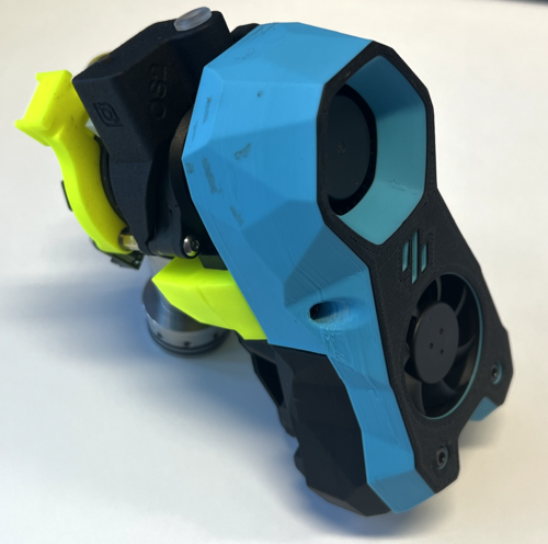
Version 1.2.5
22,243 downloads
The Mini Stealth v2 toolhead is up on GitHub now. I will keep these files here as the new parts are not compatible with the v1.2.5 parts. I will support both versions in the comments here. I still need to create new assembly instructions but a lot of the steps are similar to what is described here. --------------------------------------------------------------------------- This toolhead scales down the body of the Stealthburner to a size which fits into a V0.1/V0.2. Fully assembled it weighs about 120 grams less than the original. It is designed around the Bondtech LGX Lite extruder and has versions for the Phaetus Dragonfly, Dragon and Rapido HF hotends as well as versions for the Mosquito, the Revo Voron and the Creality Spider Pro hotends. It incorporates a status LED as well as two for print visibility. I have added new stretched versions that should fit the Rapido UHF, Dragon UHF and the VolcoMosq hotends. The Dragon UHF and Rapido UHF hotends can fit in the same shroud. The UHF hotends will reduce Z travel by 8.5mm and the VolcoMosq by 3mm. I cannot verify the fitment so if there are any issues please leave a comment. There are now two hex pattern inlays based on the design by 3DP-MAMSIH and a tutorial on how to apply them to the shroud. The negative body feature of Prusa/Super Slicer can also be used to create a crop-top version of the shroud as described at the end of the tutorial. The shroud uses a pair of 4010 blowers which produce more airflow than a 5015 blower while also being notably less noisy and drawing less current. The depth of these fans do limit Y travel by 3mm on a V0.1 while the door is closed and tophat is on. The width of the main body at its base is also a very tight fit at the extremes of X travel. The shroud fits a 3010 hotend fan or a 3007 fan by using a clip-in adapter. The Mini Stealth LGX Lite fits well in a V2.4 or Trident and modified x-frame left and right pieces are included. There is a separate 'strain_relief' stl for use in the V0.1. There are also x-frame pieces that allow this Mini Stealth to be installed on a Switchwire. The nozzle is moved up by 3mm compared to the official Switchwire. The x-frame has geometry that allows a BL-Touch to fit locked between the two pieces. I have included a magnet mount and additional shroud .stl files to make this compatible with the ZeroClick mod. This toolhead also has versions that allow mounting a differential IR sensor. I have removed the mechanical Z endstop on my V0.1 and use the IR probe as an endstop and it has greatly simplified my homing sequence. There are additional x-frame pieces that allow mounting the Beacon3D probe, Euclid or Biqu MicroProbe for a V2.4, Trident or Switchwire. The included Blender file shows the entire assembly complete with screws and should answer most basic questions. Note on MGN-9 installation: The default 2mm x 10 plastic threading screw is too long for mounting the x-axis endstop. An M2 x 8 does the job fine. For mounting to the linear carriage use four M3 x 6 flat-head screws. Note: The MGN carriage shown is an MGN-9H, not the shorter MGN-9C used in the V0.1 mod. Preparation I recommend test fitting the extruder, LGX_lite_adapter_plate, PTFE tube and hotend into the shroud before running any wires to ensure that the PTFE tube length is correct and everything fits. It helps to chamfer the edge of the tube with a sharp blade so that it doesn't snag in the hotend. I is a good idea to use a file to lightly remove any printing artifacts on the mating face of the shroud. All three fans will need the wire retention piece clipped so the wires fit into the shroud channels easier. Use a small file to smooth out the break-off edges of the LED PCB and make sure the LED pockets are clear of 'droopy bits' Differential IR Probe Installation The IR Probe needs to be screwed into place with two M2.5x8 FHCS before installing any of the fans, except with the VolcoMosq or UHF hotends where the probe needs to be glued on with CA glue. The Y-offset for this probe is 4mm in front of the nozzle and the X-offset is 32mm. I strongly recommend removing the 3-pin header and soldering wires directly to the probe PCB. When installed the wires will route out from the back of the IR probe cover to then join with the hotend and fan wires. I have included a cover to allow a connector at the probe but the wire management will be less than ideal.. Assembly Instructions After pressing the status LED diffuser into place, install the right part-cooling fan first by feeding the wires through the small hole at the bottom. Then feed the wires for the status LED and hotend fan through before starting to push the LED carrier into position. Carefully push the status LED carrier as far as it will go and press the fan into position while making sure not to pinch the part-cooling fan wires. Then press the remaining LEDs into their slots. (I measure out 35mm of wire to connect these LEDs together) Here is another view also showing how the hotend fan wires fit through the hole on the side of the status LED carrier. Insert the second part-cooling fan and splice the wires together with the first fan. Install the hotend with at least two M2.5x6 screws (M3x6 for the Revo Voron). The heater cartridge should be installed away from the LEDs to avoid overheating them. ( ** don't forget the PTFE tube ) Pre-assemble the extruder pieces before installing into the shroud. Use M3x30 screws to attach motor_bridge. Install the extruder with an M3x6 BHCS on the back and then an M3x12 from below. Ensure the cables are routed as flat to the shroud as possible and secure them with zip ties. Install the strain_relief or cable_chain_mount with two M3x8 screws and the cable_door with another M3x8 screw. Close the cable door with an M3x6 screw. Use two M3x40 BHCS to secure the toolhead to the x-carriage in a V0.1/V0.2. For installation in a Trident or V2.4 use two M3x50 BHCS. Happy Printing!23 points -
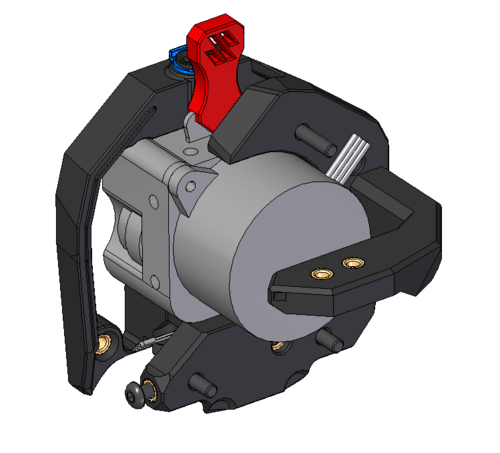
Version 2022.03.31
15,939 downloads
Orbiter 2 Clockwork Module (beta) This Clockwork module allows the use of the Orbiter v2 Extruder in the Voron Afterburner. THIS IS A PRE-RELEASE - DO NOT DOWNLOAD UNLESS YOU ARE WILLING TO DEAL WITH POSSIBLE ISSUE OR TO GIVE FEEDBACK! The rear screws that hold the chain anchor on are m3x8, two of them. They use the Voron heat set inserts, m3 I was working with DoubleT on the PCB holder. Trying to build a universal tool version so we could use different holders.22 points -
Version 1.0.0
10,982 downloads
Hex mesh skirts for Voron 2.4, with matching fan grills and Z motor covers. The skirts are obviously remixed versions of the default Voron designs. The fan grill and motor covers are my own creations. The center, side, fan supports have been modified so that they fit onto the printer backwards. You will need to install one additional heat set insert into the front of the fan (4 total in the front), and add 3 to the back. Three m3x8 screws hold the fan into the support from the backside, and four m3x8 screws hold the fan grill onto the front. Included is a model file for a 6020 fan blank. This blank will allow you to mount the grills on the side opposite that which has the fans, while maintaining the same appearance as the side with the fans. For multi-color prints, just swap out your filament at the layer above the hex mesh. I have included .stp files, to make it easier for anyone who would like to remix.21 points -
Version 1.0.0
4,493 downloads
Orbiter 1.5 on SB 20/04/2022 .step available my config rotation_distance: 35.1 gear_ratio: 75:10 microsteps: 32 full_steps_per_rotation: 200 #200 for 1.8 degree, 400 for 0.9 degree nozzle_diameter: 0.400 filament_diameter: 1.75 max_extrude_only_velocity: 60 thanks to Eytecz (https://github.com/Eytecz/LGX_Lite_Stealthburner_CW2_style_mount/ ) for his mount of lgx lite on SB to inspire me to complet this orbiter 1.5 . i hope you like it19 points -
Version 1.0.0
171 downloads
Dear All, This is a very simple modification to the Main Body of the Stealthburner Clockwork 2, to improve performance when printing TPU. I found that when printing TPU, particularly the softer Shore hardnesses, the extruder would frequently skip, stutter and misbehave, causing poor quality prints. After studying the CAD files, I reasoned that as the direct drive outputs the filament into a bore in the Main Body, before the PTFE tube, the filament might be compressing at this point, and jamming up in the higher friction printed plastic. To remove this issue, I continued the 4.2mm bore for the PTFE tube all the way up into the direct drive chamber. This allows the PTFE tube to be extended, and carefully cut (with a scalpel, or craft knife), to exactly match the direct drive gear. With this change, the filament outputs from the direct drive gear directly into the PTFE tube, with no opportunity to touch the higher friction printed plastic, and no space to jam up in. I have found that this simple modification dramatically improves performance with printing TPU on my printer. Hopefully it'll do the same for you. Note that getting the length of the PTFE tube exactly right with this arrangement is a little bit tricky. Cut the tube too short, and you'll be left with a gap that the TPU can compress into (giving you the same problem), but too long will cause it to foul/drag on the direct drive gear. Easiest thing to do is to sort this out first, before you build the rest of the Clockwork. Fit a length of PTFE tube to the Toolhead & holder of your choice, and cut it so that ~25mm is extending from the top. Slot this into the CW Main Body, and the tube should end approximately half way across the direct drive gear chamber. You can then use the sharp scalpel/craft knife to follow the contour of the chamber, as shown in the photograph attached. Hope this is helpful! Best regards,18 points -
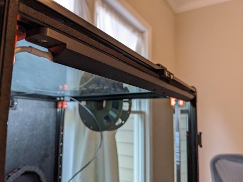
Version 2021.12.07
1,426 downloads
Hidden cable routing z belt cover mod Credit Mod based on the design of the Voron crew. Thank you for your awesome work! Print settings As stated in the Voron documentation: ABS 0.2mm layer hight 0.4mm extrusion width 40% infill wall count 4 top/bottom layers 5 no supports Bom Only the printed file. Improvement Added the possibility to route cables on the bottom of the cover. Description I liked the design of the old Voron 2.2 covers more than the current design so I based my mod on them. This mod allows to route cables that are hidden in the extrusions to the bottom compartment. To achieve that the inner part of the z belt cover is a bit thicker and a path is cut out on the bottom where cables can be routed. The overall dimensions are the same as the stock 2.2 covers. Note: Be careful to restrict the cable in the bottom compartment so it does not rub on your z-belts. Pictures Top:18 points -
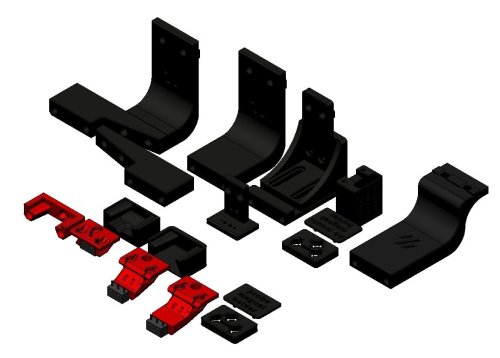
Version 1.1.0
3,257 downloads
Converts the current Voron v0.1 panel mounting parts into easily removeable magnetic mounts. Perfect for switching between ABS/PLA without the hassle of unscrewing everytime. Mounts using the basic m3x8 hardware that the original parts mounted with. Included are the files for a spacer to fill the gap between the frame and the panels to help with heat loss, this is not needed but will help. I have installed some 12mmx6mm adhesive draft excluder found easily on amazon. You will need to print 8 of each "part 1" and "part 2" to fit each side, they will not totally fill the gap, there is a small space left on the top and bottom to allow gripping the panel to remove it. Required hardware: 16x m3x8 (original hardware) 16x m3 nut (original hardware) 16x 8mmx2mm neodymium magnets (You can source easy enough, but here is a link to the ones i have used from UK Amazon; https://www.amazon.co.uk/Magnet-Expert%C2%AE-8mm-thick-Neodymium/dp/B007JTL25M/ref=sr_1_2?crid=VG4LDUUBDICR&keywords=8mmx2mm+magnet&qid=1647471673&sprefix=8mmx2mm+magnet%2Caps%2C48&sr=8-2 ) Optional hardware: 2m 6mm thick adhesive draft excluder 32x m3x8 32x m3 nut17 points -
Version 2022.05.03
382 downloads
Stealthburner Clockwork1 PCB Cover I designed a cover for users who are still rocking the CW1 with Stealthburner, with the same low-poly esthetic of stealthburner. This cover is a snug fit, so please make sure your wiring is all nice and tidy or you could have some issues.17 points -
Version 1.0.0
783 downloads
StealthOrbiter This mod aims to mount the orbiter V2.0 extruder to the stealthburner assembly. In addition, it incorporates the Orbiter filament sensor to enable support for the ERCF. There are a number of different versions, depending on your configuration: Standard mount Standard mount, with PG7 cable gland Filament sensor mount Filament sensor mount, with PG7 cable gland The most up to date files can be found on the github repo Acknowledgments - spacelab_2021, for providing the starting point I used in developing this mod17 points -
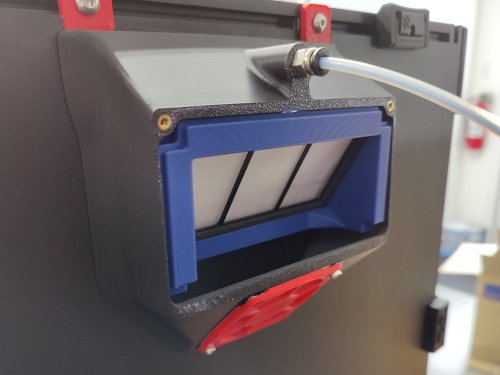
Version 29.12.22
1,042 downloads
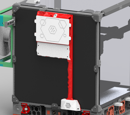
Burst from Discord Voron asked my if I can do an update of my old "HEPA + activated carbon Air filter mod" for his new machine: he wanted wiring for CanBus and ERCF I made it and added some "stealth" to it. Work in progress... This is based on Fanny Pack Air Filter. I dont know who made it originally.17 points -
Version 1.0.0
2,412 downloads
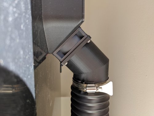
I wanted to be able to print ABS and ASA in my house without having to move my printer to a well ventilated area, so I started looking into ventilation options. I wasn't able to find anything that seemed to mount cleanly to my machine and look decent running to my window, so I designed this system for my printer. BOM: Parts to order 2.5" Hose Clamps x2 2.5" Flexible Dust Collector Hose (3ft in picture) x1 Weather Stripping (10ft in picture) M2 self-tapping screw Plastic Sheet (1.5mm-2mm) Parts to Print 60mm Fan to 2.5" Hose Adaptor x1 Hose Adaptor x1 Hose Adaptor Mount x1 One-way Valve x1 Left Link x1 Right Link x1 Center Link x? (You will need to measure your window for the proper number of links) Printing: 40% infill Supports needed 4 line walls Filament: Polymaker's Polylite ASA If you are using the stock Voron 2.4 exhaust system, you can attach the hose adaptor directly to the rear fan using the screws already holding the fan in place. All of the links snap very tightly together and may require pliers to fully seat the lock. You can also insert the one way valve into the hose adapter on the window side of the hose: Then just attach all of the other pieces according to the images below: Once you have everything hooked together your can wrap the window vent that is now sized for your window with the weather stripping to get a good seal on your window. One note, I was printing several test versions of this before I got to a full system. There are couple links you will see in the center of my image that have a smaller lip on them. I just reused these from previous test pieces so I didn't waste more plastic. Your center links should be consistent all the way across the middle section of the window vent. UPDATE: 3/9/2022 - Added a one-way valve to prevent outside air from causing a backdraft into your printer when your exhaust fan is disabled. This has made a significant impact on reducing plastic fumes in my house. After adding this, I can't smell any plastic unless the doors on the printer are open. VORON2 v2.4 - 2.5 Vaccume exhaust adapter v4.f3d16 points -
Version 1.0.0
477 downloads
LGX_Lite_Stealthburner_CW2_style_mount LGX Lite extruder mount for the Voron Stealthburner. The standard bowden clip delivered with the LGX Lite is to be removed, and a standard UM2 connector has to be inserted in the top printed part. This style clip is to be used: https://nl.aliexpress.com/item/32896103430.html. If you're lucky you might have some laying around already. LGX Lite mount ERCF The ERCF version is made to accomodate the LGX Lite with the stealthburner and the new carriage, including the toolhead sensor as it is being used for the ERCF. The housing style is matching with the original CW2 design. I recommend to insert a 3mm long 4x2mm bowden tube on the bottom of the LGX Lite to guide the filament properly. The cover and cable carrier mount can be re-used from the original version. The top of the front body is made to insert the bowden tube until it reaches into the LGX Lite, through a standard bowden tube clip with retainer ring. A lever latch is designed to change the pretension on the filament. The toolhead sensor is a standard hall effect switch (AH3364Q-P-B), which can be soldered to some wires with a connector. This sensor enters in between both halves of the support body and can be fixed using an angled M3x8 DIN912 bolt. Please be careful not to overtighten this bolt as it clamps directly onto the sensor housing. A standard washer M3 is to be inserted in the slot centered with the filament path. The magnet can be inserted in the front. Be sure to check the correct polarity. To mount the LGX Lite to the body, use the 4 screws DIN912 M3x16mm, too long screws will damage the gears within the LGX! M3 Threaded insert locations In the front housing there are 2 threaded inserts M3 which needs to be placed on the 'inside' to fixate the actual Stealthburner cover to. In the rear housing there are 4 threaded inserts M3 to be placed on the back as shown in the image below. Cable hatch and cable carrier The standard cable door hatch and cable carrier support can be re-used from the original CW2. Be sure to mount the cable door before mounting the LGX Lite into the housing. You won't be able to reach the fastener once the LGX Lite is placed. I am not responsible in any way on how this impacts your printer. Use at your own risk.16 points -
Version 1.0.1
492 downloads
This is a remix of Demosth's excellent Skirt Fan Mount. I found the stock fan mount to be flimsy and easy to break off the extrusion. Demosth's version is a lot better but still only uses a single screw. I also wanted to use my red fan grills for extra flair. I added three additional features: 4 more holes to secure the mount to the extrusion any way you want (if using the outer most holes, you'll need to attach the mount to the extrusion first before attaching the fans and grills). You can still only use a single screw to mount it on the extrusion if you're feeling lucky, but I recommend using at least two. 3mm through holes to allow using custom fan grills (just as on the stock fan mount, you'll need to add heat inserts to the fans). Side profile for a snug and elegant fit against the part A and B side skirts, adds to the overal sturdiness of the assembly. This version is provided in 3 variants: Solid_Skirt_Fan_Mount_Channel: with profile walls and cable channel Solid_Skirt_Fan_Mount: with profile walls, no cable channel Solid_Skirt_Fan_Mount_Open: without profile walls on the side. (no idea why you'd want this one) All models are watertight and print as normal. No supports needed.16 points -
Version 1.0.0
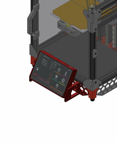
611 downloads
This work is based on sttts's Waveshare 5.5inch mount. BTT PITFT50 v2 has a different layout than v1, featuring a brightness thumbwheel, an orientation switch and a JST XH port for unknown function. This design provide accessibility to the thumbwheel and switch. BOM 4x M3x6mm 4x M2.5x4mm (included in the BTT PITFT50 v2) 500mm ~ 600mm Ribbon Flat Cable for Raspberry Pi Camera (depends on the position of the Raspberry Pi. The included one is too short) Instructions Please use the mount in sttts's mods to amount this to the frame. No re-print of skirts is required! Print Settings Standard Voron recommended print settings16 points -
Version 2022.03.31
6,344 downloads
Microswitch probe with magnetic attachment, primarily aimed at CoreXY 3d printers with a focus on the Voron printers, should work on other printers with the variable mount. The objectives for this project are: drop in replacement for Omron TL-Q5MC2 or PL-08N2 (you don't need to replace the toolhead) easier and faster to build than similar probe types does not require soldering fixed probe dock mount (for the printers that are suported), less variables to adjust be able to detect all the print surfaces be as close to the hotend tip as possible highly repeatable and accurate probes less temperature variations no melting of its parts cheap to build It can also be used with the new automatic Z calibration klipper plugin to effectively calculate the Z offset from the probe and from the Z endstop. The inspiration for the Klicky Probe comes from the Annex magprobe and the Euclid probe, it uses some concepts from each of the projects. There is no need for supports, recommended settings are 4 perimeters/top/bottom, 13% infill. The probe dock is mounted on the gantry, allowing it to be used as a Z endstop if desired (I use it that way). There are three gantry extrusion mounts possible: one fixed to be used on the Voron V2.4 or V1.8 AB with MGN12 or MGN9 - one that has some variance for other toolheads - one fixed sidemount dock to allow a purge/scrub bucket on the left side of the bed The fixed gantry extrusion mounts have been confirmed to work on the Voron V2.4 and V1.8 The normal magnet installation is that the two magnets that attach to the microswitch are installed with the same polarity, the 3rd magnet should have the inverse polarity. There is however the possibility that the magnets will demagnetize over time due to the alternating magnetic fields thay may result in a slow but sure demagnetization of the magnets, the magnets are so strong that may take a long time to show the effects of demagnetization YMMV. No soldering is necessary, the probe microswitch connectors are also press-fit on the magnets. The AB mount wires are also connected with pressure from the magnets, you can use the probe magnets as a template to insert the AB mount magnets, it is easier that way to don't insert the magnets the wrong way. You will not lose Y travel on any configuration in the tests that were done. It is also recommended to glue the magnets in place, superglue is good. You will need to add macros to Klipper to be able to dock and undock the probe as necessary to do the Endstop (if necessary) and Quad Gantry Level, it is in the Klipper Macro directory. Probe BOM: 1x microswitch (the omron D2F-5 or D2F-5L (removing the lever) is recommended) 2x M2x10 self tapping 4x 6x3 magnets AB mount BOM: 3x 6x3 magnets Probe Dock: 1x 6x3 magnets 2x M3x20 Fixed Dock mount: 2x M3 threaded insert M3x5x4 2x M5x10 2x M5 t-nut or equivalent or variable Dock mount: 10x M3 threaded insert M3x5x4 8x M3x8 2x M5x10 2x M5 t-nut or equivalent If you would like to check a possibly more uptodate repository, check here The macro is based on a version provided by the user garrettwp on Discord, many thanks to him. I have tweaked it a lot. It is also originally based on the great Annex magnet dockable probe macros "#Originally developed by Mental, modified for better use on K-series printers by RyanG and Trails" and can be found here Would also like to thank the Voron discord community and VoronDesign for all the work that was and still is being made to maintain the Voron ecosystem. The probe accuracy output is something like this: probe accuracy results: maximum 6.430000, minimum 6.426250, range 0.003750, average 6.428750, median 6.428750, standard deviation 0.000791 There is now an arrow on the probe telling you where should the switch pole be to have the correct offset. The probe offsets are: z_offset = 6.42 x_offset: 0 y_offset: 19.75 Assembled Klicky Probe Dock and undock video It is working very well, if you decide to use it, give me feedback, either here, or on discord, my discord user is JosAr#0517. By standing on the shoulders of giants, let's see if we can see further.16 points -
Version 2021.12.07
732 downloads
Angry CAM USB Please find my USB Camera Mod based on Waveshare OV5648 5MP USB Camera Module (A), which allows mounting to rear gantry or other position on a frame profile. Printing Printing succesful with standard VORON settings. Distance between mounts and camera housing set to 0.3 mm in *.stl file, which allows printing of mounts and housing in one print. Use the following two *.stl files for realization in one print: Camera_Housing Mounts.stl Rear_Cover.stl Additional Material Bill of Material: 1x Waveshare OV5648 5 MP Camera Module (A), incl. USB-A to JST SH PCB connector cable 2x M3x16 SHCS screws 2x M3 T-Nut for 2020 frame profile 1x Camera Housing Mounts and Rear Cover from the printing source of your trust. Optional/Required for frame sizes15 points -
Version 1.0.0
6,082 downloads
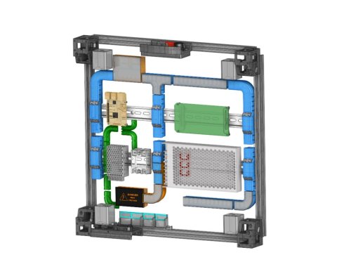
This Remix of RyanDam's Cable Management Duct for Voron Printers includes a number of custom ducts which I am using in my Voron 2.4 build. Thanks to the original author for the excellent design of the ducts, which this remix is based on! Since these models are designed to work with electrical components, if you use these models, it is at your own risk. Included here are several customized ducts which may help with cable management in a Voron build. I am still in the process of building mine, and I chose to use the same electronics layout as the voron spec. These ducts were designed based on my FYSETC R2.4 kit (which I am building as an R2.4 V2), so some dimensions may be different in other kits. This was designed with help from the STEP file from the Voron Github. There are several ducts included, which are designed to go over the DIN rails, and these parts include “BRIDGE” in their names. These parts will need to be printed with supports. There is an integrated support in the “HALF_BRIDGE” part, but that could also be printed with supports if needed. The “HALF_BRIDGE” part also has a thin raft like integrated support which will need to be removed. The 90 degree full bridge ducts are slightly different between the right hand (RH) and left hand (LH) versions. The difference is that the RH version (Cable_Management_Duct_Remix_DUCT-FULL-BRIDGE_90DEG_RH_5B.stl) is cut off a bit short to allow the power supply stabilization bracket to pass. I set my ducts up so that the high voltage AC wires, and the low voltage DC wires, would stay in separate ducts. To do this, I used two half ducts (one for the AC, and one for DC), on the center duct which crosses the lower DIN rail in the pics, which is nearest the power supply. I also printed the AC ducts in orange so they would be distinctive as a reminder they contain the high voltage AC wires. There are also plain and logo versions of the covers. The covers for the “BRIDGE” parts have print in place hinges, so if you find they are welded together when printed, it will be helpful to calibrate flow and horizontal expansion, as well as adjust the temps for the filament used. I made some minor improvements to parts since I printed mine (either for length or printability), but I do not think there will be any issues due to the changes. I printed the ducts for my printer in ABS and PETG, but use your best judgement on the appropriate material to use. I used VHB tape to secure them, but just note that once placed, they won't likely be going anywhere soon. Parts are not oriented for printing. Feedback is welcome, and if there is a problem I will try to fix it as I have time. I'm still building my printer, so if I run into an issue with this design, I will update it further, however I don't foresee any interference issues currently. Most likely I will not be able to accommodate requests to customize these further. The STEP files can be found on Printables (since the file was too large for this site), so remixing will be simpler. If you print these, or use these, it is at your own risk. I posted some remix covers for the boxes, which have inset printed labels, as well as some single and double wire guides which I am using to secure my ground wires. If you find these models useful, please post a like or a comment with some pics of your prints. You can find some other things I am working on at my blog (https://www.mystoopidstuff.com/blog), thanks for looking! You can find some additional low profile wire guides here: https://www.printables.com/model/502345-wire-management-guides There is a remix of the small box (not included here but shown in the pics), which holds two WAGO 221-415 connectors here: https://www.printables.com/model/505826-wago-box-for-the-remix-of-ryandams-cable-managemen The AC caution covers, with inset text and warning symbols for the small box and half bridge duct, can can be found here: https://www.printables.com/model/505838-ac-caution-covers-for-remix-of-ryandams-cable-mana/files15 points -
Version 2.0.0
304 downloads
My printer weighs close to 100lbs and half of that is glass panels. I don't trust current handle designs for that kind of weight but I needed something to make my printer movable. Each one needs 2 screws: 2 x m4-18mm and 2 x m4 t-nuts. The handle is designed to load the extrusions along the inserted ridges. The screws are mostly there to keep it fully inserted; in fact, the handle clips on the frame and hold there without the screws! These handles will make it possible for two people to firmly hold the printer and carry it. STL needs to be mirrored to make a proper pair and 2 pairs needed for a full set. Hinge Clarence: Version 1 installed (v2 looks the same)15 points -
Version 1.0.0
866 downloads
2 Parts Mounts snap in place 0.2 layer Height 20% infil i hope this help15 points -
Version 2021.08.24
15,623 downloads
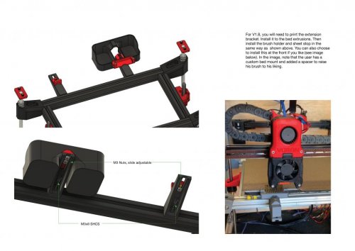
A Team Dropbear Production (Note this mod is no longer maintained but is kept for historical purposes.) Decontaminator Purge Bucket & Nozzle Scrubber This is a removable purge bucket with a nozzle scrubber. It is compatible with Voron 1.8 and Voron 2 printers (v2.4, v2.2 and v2.1). I noticed that the current nozzle scrubber design of the Voron was not very effective at containing filament debris and bits. It was also not removeable, making it a pain to reach behind and clean it out with a vacuum. So, this design aims to solve all that by: Making a larger and deeper purge bucket to hold more filament gunk. Purge bucket is removeable and naturally clips onto the brush scrubber with its geometry. Magnets help secure it further with the added benefit of a satisfying 'clip' sound when attached. A spring steel sheet stop/index is provided for convenience when putting your spring steel sheet back on the plate. These use M2x10 self tapping screws that allow you adjust the height so that they're flush with the print surface. Installation & Parts Required Pictures shown are slightly older versions, however, installation is exactly the same. The geometry of the brush_holder is such that it clips and holds the brush in place through friction fit. As noted in the installation guide, do not try to force the brush in if it's the wrong size; it will break quite easily. For V1.8, you will need to print extension_bracket_v1.8 (print 2x if you want to use the individual sheetstop). Some may opt to install it at the front. You will need the following: 1x brass brush or whatever you prefer (I got the TriangleLabs brass/copper brush and cut it down to length). For V2.1, 2.2 & 2.4: 2x M3x8mm SHCS (3x if you use the sheet stop option) For V1.8: 3x M3x8mm SHCS (5x if you use the sheet stop option). 2~3x M2x10(or 8, or longer)mm self tapping BHCS/SHCS (optional if you wish to use the sheet stop function). You should have these from the V1 and V2 BOM which are spec'ed for the microswitches. 2~3x M3 nuts (for V1.8 only) 2x 6x3mm round magnets STLs are included here and CAD files as well if you wish to change the dimensions or modify to your liking. A purge and nozzle scrub macro that is plug and play is provided as well; you can find them under Macros. Shoutout to community member Hernsl for providing this macro! NOTE: If you are using the z endstop from V2.2, there is a version of the stop that takes into account the locating bolt heads of the endstop. You can simply mirror the stop in your slicer if your endstop is on the other side of the extrusion. HISTORY OF REVISIONS The purge bucket & nozzle scrubber has undergone many revisions within a short time, especially between Rev3 and Rev4. To avoid confusion and provide clarifications to current users of the purge bucket and prospective users, please read the following: Rev1+2 and Rev3 are intercompatible with each other. They only work on V2.2 and V2.4. Rev4 is a completely standalone revision (only individual sheetstop remains unchanged, rest are not backwards compatible with Rev1+2 and Rev3 and vice versa). This revision works on V1.8, V2.1, V2.2 and V2.4 and the same parts are shared across all platforms. You will be able to find these older revisions under Legacy_Revisions. REV1+2 AND REV3 In Rev1+2, the brush holder was available as two options: a regular holder and one with fully printed sheet indexing stops. In Rev3, the brush holder became only available as a printed sheet stop option with M2X10 BCHS self tapping screws. Purge buckets were compatible across Rev1+2 and Rev3. REV4 (LATEST) V1.8 support was added in this revision. Due to screw distances changing in V1.8 to allow clearance from the rear electronics panel, I made the decision to have this change apply to the V2 versions so that one part can be used across V1 and V2. This would minimise hunting for specific parts for each specific printer. However, this means that only the individual_sheetstop carries over from previous revisions (purge bucket dimensions have changed as well). Future revisions may include the use of a silicone brush that is gentler on plated nozzles. Come back for updates! -edwardyeeks (edwardyeeks#6042)15 points -
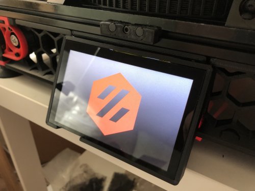
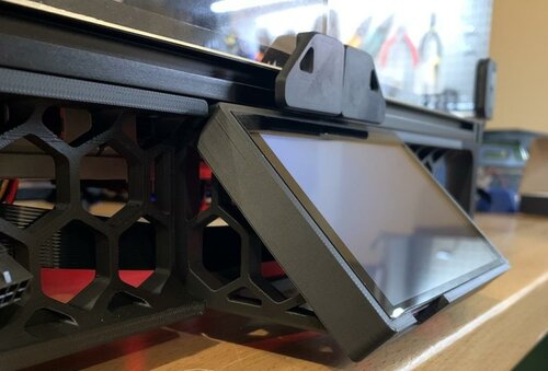
Version 1.0.0
1,084 downloads
This is a flip down TFT50 screen mount for the Voron V0.1. It's still a work in progress but it works and allows the screen to fold down so the door can be opened.15 points -
Version 2022.05.09
971 downloads
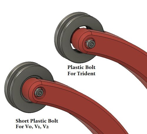
Horseshoe Spool Holder This is a method to mount the filament spool inside the enclosure of a Voron Trident 3d printer, or outside a V0, V1 or V2 printer. It works with 200mm, 1kg spools only. For mounting internally in the Trident, the ptfe tube is installed as shown: up through the gap in the side of the rear extrusion. Alternately you could drill a 4mm hole though the B stepper mount top and bottom parts. To install the spool: Feed the filament through the ptfe first, then align the spool into the front and top bearing rings, and pull forward to spring the frame and drop into the rear bearing ring. BOM: 3 608 bearings (any type) 2 M5-8mm (pan/socket) head bolts and 2 M5-Tnuts for 2020 extrusion only OR 4 M3-8mm (pan/socket) head bolts and 4 M3-Tnuts for 1515 extrusion 3 - M3-8mm bolts (pan/socket) Internal Version for Trident only Print PlasticBolt(x3) and use a m3-8mm PH or SH bolt to secure the pin in place. External version for V0, V1, V2 Print ShortPlasticBolt(3x) and use a m3-8mm PH or SH bolt to secure the pin in place. Please provide feedback for issues/suggestions to #Logan2225 on VoronDesign Discord. Thanks!15 points -
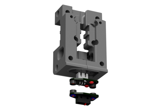
Version 1.0.1
465 downloads
Stealth Burner X-carriage Euclid probe 2.4/Trident / MGN 12 left Right mounting the EUCLID probe with self taping m3x8mm screws this X-carriage is remixed from https://github.com/VoronDesign/Voron-Afterburner/tree/sb-beta/STLs/X_Carriage I hope this helps15 points -
Version 2021.12.15
3,051 downloads
270 Degree Clamping Hinges The design of this hinge is based on chrisgonzales already incredible 270 degree hinges. The main goal of this remix was to have the front panels mounted in a way that didn't use any VHB tape or holes that needed to be drilled into the acrylic, and of course, use minimal amounts of additional hardware. After many design iterations and improvements I came to a solution. Important Notice If you're going for a super sealed enclosure, then these hinges are not for you. In testing ( at the moment with only 2 hinges per panel ) I found after opening and closing the doors several times, they would slowly lose alignment ( only by fractions of a mm ) and just need a little push to re-align so the panels would close properly and not collide. This means you'll probably have a gap of a couple mm between the panels at the front if you don't want to be driven crazy by them not staying super aligned. A potential fix would be to print 3 hinges for each panel but I am yet to test this although I strongly recommend you do use 3 hinges per panel if you have a printer larger than 250x250 ( what I'm testing them on ). Update Log 11.12.21 - Made subtle changes to dimensions to hold panels closer together whilst having them fully seated in the clamps for maximum strength, also changed recommended print settings for stronger face_plate_bottom.stl. Using Foam Tape At the moment I have only tested using 3mm thick foam and that works well, you may be able to get away with 4mm foam, but for anything thicker, you'll need to modify part of the hinge to accommodate this. Keeping The Doors Shut I am currently using clamps designed by v6cl Different Styles Of Face Plates The file names match up with the digrams below. Face Plate No Logo Face Plate Embossed Logo Face Plate Through Logo BOM - Per Hinge Printed Parts face_plate_top.stl [x1] face_plate_bottom.stl [x1] side_mount.stl [x1] Additional Hardware M3 x 8mm SHCS [x5] M3 Hex Nuts [x2] M3 T-Nut [x1] Printing I recommend following the default settings for Voron Parts, and none of the parts require support material. Layer Height : 0.2 mm Extrusion Width : 0.4 mm Infill : 40 % ( 100% For face_plate_bottom.stl ) Perimeters : 4 Solid Top/Bottom : 5 Supports : No Brim : Optional Assembly Better photos will come in good time Attach the _face_platebottom to the _face_platetop using 2x M3 x 8 mm Bolts and 2x Hex Nuts - Keep the bolts loose for now Attach the faceplate assembly to the _sidemount using 2x M3 x 8 mm Bolts - Again, don't overtighten these so the hinge moves easily Install the finished hinge assembly to the frame using 1x M3 T-Nut and 1x M3x8mm Bolt - Position them now to your liking Once all the hinges are on the frame. Slot in a panel on one side, before tightening down the M3x8mm Bolts in the faceplate assembly. And repeat for the other panel. Loosen the panel's clamps and position accordingly, repeat for the other panel. For the handles, I just re-used the correct ones that chrisgonzales made :). Installed On My 2.4 Better photos will come in good time15 points -
Version 2022.05.23
1,011 downloads
20x20mm, slot 6 Profile Covers Please find here my mod for variable profile covers for 20x20 construction profiles with 6mm slot. Printing Printing successful with standard VORON settings. For adjusting the length of the profiles you can scale the *.stl file in your slicer in y-direction after import and before positioning (rotating/placement) on your print bed. Please find the following example on how to do so for SuperSlicer: Sequence: Deactivate linked scaling with click on lock symbol, Lock symbol status (15 points -
Version 2022.04.21
2,652 downloads
This is a simple mount for attaching wago 221-41x to extrusion: by power inlet and under bed, or to Din Rails, for smaller builds. BOM - 2x M5-10mm bolts This is a simple angled mount for wago 221-41x blocks in sets of 3 that mount to a din rail using the Trident power supply din rail clip. Original design by Socal3D on voron discord, I just cleaned up the design and added the mount. BOM - 2x M3-8mm bolts, Wago 221-41x15 points -
Version 2021.03.20
875 downloads
STL File You can print this logo on your 3D printer. I have included base (0.64mm thick) in this stl file which you can print in base color (at 0.24 first layer + two 0.2mm layers) & change filament after 3 or 4 layers to your accent color. I changed filament after 4 layers. Use monotonic top layer infill to have uniform top layer of Black base. Check images below. Use VHB tape to stick it to back panel. Image Files Image files are included in high quality JPG & PNG format if anyone wants to print them on paper with traditional ink printer. DXF File DXF file is included if anyone wants to cut this on laser cutter out of Vinyl wrap. (Like I did, Shown in Images below)15 points -
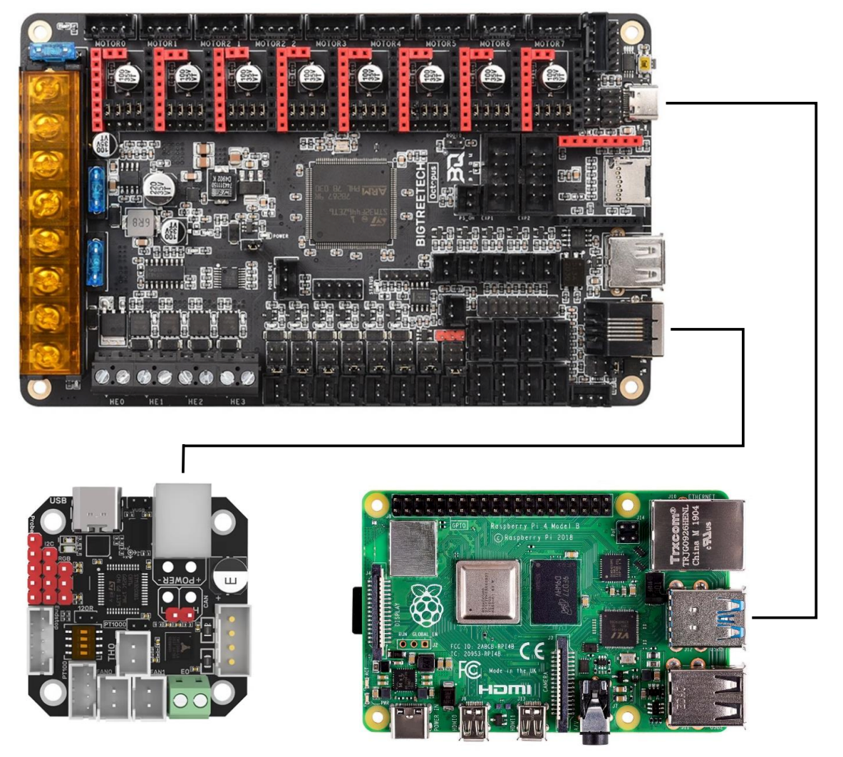
I found this Canbus with CanBoot and Octopus excellent guide on Facebook, posted by TJ M. Wanted to share it with the community and make it easier to find! How to Use CAN Toolhead Boards Connected Directly to Octopus / Octopus Pro on CanBoot Klipper has a new CAN bus feature, the USB to CAN bus bridge communication for Octopus boards (and other compatible MCUs). This feature allows the Octopus boards (and other compatible MCUs) to act as a USB to CAN bus adapter. This replaces the need for an adapter like a Raspberry Pi CAN HAT, canable adapter, or the Bigtreetech U2C board. What is CanBoot? CanBoot is a custom bootloader loaded onto your Octopus and EBB board that allows users to update Klipper firmware over USB, UART, or CAN comms without physically having to access the board reset buttons or BOOT jumpers. It uses the same ‘make menuconfig’ setup to configure and compile firmware. CanBoot is NOT required to use the Klipper USB to CAN bus bridge comms. But I have not tested this comms feature separately. You Will Need the Following USB-A to USB-C cable Power supply for Octopus and EBB toolboard (i.e. printer) RJ11 or RJ12 telephone cable, crimped to connect EBB board to Octopus See wiring info at end of guide. Best to setup wiring before installing software. Raspberry Pi, or similar, with Klipper / Moonraker / UI installed and working Computer with following software: SSH terminal software, I use PuTTY or Windows CMD WinSCP, to transfer files between Raspberry Pi and computer I also use Windows CMD to do this STM32CubeProgrammer Download for your computer OS and install https://www.st.com/en/development-tools/stm32cubeprog.html#getsoftware High Level Instructions, for Understanding Install CanBoot on Raspberry Pi, flash firmware to boards Configure and compile CanBoot firmware for Octopus / Pro and EBB Flash CanBoot to boards using STM32CubeProgrammer and computer Setup boards for Klipper Octopus - Setup Klipper for USB to CAN bus bridge, with CAN comms to EBB EBB - Setup Klipper for CAN comms Find serial device for Octopus / Pro on Raspberry Pi Flash Klipper to Octopus / Pro with CanBoot serial command Setup can0 network on Raspberry Pi, power cycle printer Find CAN uuid for Boards a. Connect EBB to Octopus / Pro, power cycle printer Flash Klipper to EBB board with CanBoot CAN command Printer Config Update and General Tips How to Use CanBoot to update boards, Tips Okay, enough talking! Let’s get started! (download the FULL 25 Page guide below! How to Use CAN Toolhead Boards Connected Directly to Octopus.pdf
14 points
-
Version 1.0.0
308 downloads
I have made modifications to use M3 DIN7380 screws. Much less random than if you use filament as pins.14 points -
Version 1.0.0
98 downloads
A proper filter box for using Roomba 800/900 series HEPA filter in your Voron 2.4 Exhaust. Unlike the other HEPA box posted here, this one fits the original exhaust housing and should use less material. Print with Filter insert side on bed with support on build plate only. To install it in the exhaust box, insert it at 90C angle and rotate it as you insert (last pic). The last push to lock it in place might require you to push from inside the printer. You might have to temporarely remove the fan for installation!14 points -
Version 1.0.0
554 downloads
This is a two piece LED strip mount. It accommodates 7mm-8mm LED strips and mounts them to 2020 extrusion at a fixed 45 degree angle. BOM: Printed Male Mount Printed Male Mount - 1 Printed Female Mount - 1 3mm Socket Head Bolt - 4 3mm T-nut - 4 Strip of 7mm-8mm led lights Notes: This was specifically designed to fit my 350x350 build. It would likely need to be scaled down to fit smaller v2.4s I'll add a better wiring photo once I get it cleaned up14 points -
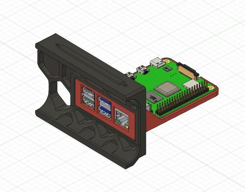
Version 2022.04.16
1,038 downloads
If you want to mount your Raspberry Pi so the usb and ethernet ports are externally accessable, look no further. Supported: Pi 3B/4B and Trident or Voron 2.4 machines. New Support added for Voron 2.4 250 size, and all 3 sizes of V2.4r2 BOM: Uses stock hardware, no additional parts required. M2 screws for Pi to plate, other hardware is the same as stock skirt installation.14 points -
Version 2022.04.07
391 downloads
BTT PITFT50 45-degree Mount This mod is an alternative frame mount for alanho's PITFT50 screen mount. They suggest using the frame mount from sttts, which puts the screen at a 30-degree angle. I found that with the shorter guitar amplifier feet on the Trident and 2.4r2, the 30-degree mount makes the screen assembly too tall to fit under the frame. This mod replaces the 30-degree frame mount with a 45-degree mount, which provides plenty of clearance. This design was created from scratch, but was heavily inspired by other mods: roboticator24 - 4-inch Touchscreen Mount jeoje - 4.3-inch Touchscreen Mount sttts - Waveshare 5.5inch HDMI AMOLED Mount This was tested with a BTT PITFT50 v2, but will likely also work with sttts's 5.5-inch Waveshare mount, since the hole pattern is the same. Bill of Materials 6x M3x8 SHCS 2x M3 T-Nuts alanho's PITFT50 mount Assembly Instructions Assemble the screen mount Use 4x M3x8 SHCS to attach the frame mount to the screen mount Insert 2x M3 T-nuts into the bottom of the frame Thread 2x M3x8 SHCS into the T-nuts to attach the mount to the frame Printing I printed with standard Voron settings, but this would probably be fine with fewer walls and less infill. I found this part very prone to warping, so you may want to use a brim or ears.14 points -
Version 1.2.5
13,495 downloads
The Mini Stealth v2 toolhead is up on GitHub now. I will keep these files here as the new parts are not compatible with the v1.2.5 parts. I will support both versions in the comments here. I still need to create new assembly instructions but a lot of the steps are similar to what is described here. --------------------------------------------------------------------------- This toolhead scales down the body of the Stealthburner to a size which fits into a V0.1/V0.2. Fully assembled it weighs about 80 grams less than the original. It is designed around the Orbiter 1.5 extruder and has versions for the Phaetus Dragonfly, Dragon and Rapido HF hotends as well as versions for the Mosquito and the Revo Voron hotends. It incorporates a status LED as well as two for print visibility. There are now two hex pattern inlays based on the design by 3DP-MAMSIH and a tutorial on how to apply them to the shroud. The negative body feature of Prusa/Super Slicer can also be used to create a crop-top version of the shroud as described at the end of the tutorial. I have added new stretched versions that should fit the Rapido UHF, Dragon UHF and the VolcoMosq hotends. The Dragon UHF and Rapido UHF hotends can fit in the same shroud. The UHF hotends will reduce Z travel by 8.5mm and the VolcoMosq by 3mm. I cannot verify the fitment so if there are any issues please leave a comment. It uses a pair of 4010 blowers which I found to produce more airflow than a 5015 blower while being notably less noisy and drawing less current. The depth of these fans do limit Y travel by 3mm on a V0.1 while the door is closed and tophat is on. The width of the main body at its base is also a very tight fit at the extremes of X travel. I have raised my tophat by 20mm which gives the cabling and filament tube plenty of room to breathe. The shroud fits a 3010 hotend fan or a 3007 fan by using a clip-in adapter. I have also installed this on my Trident. The included files do not address cable management on a Trident or V2.4 but do provide mounting to the MGN12 carriage. The cable chain on a Trident or V2.4 would have to be moved back at least 5mm to clear the extruder stepper motor. There is a separate 'strain_relief' stl for use in the V0.1. There are also x-frame pieces that allow this Mini Stealth to be installed on a Switchwire. The nozzle is moved up by 3mm compared to the official Switchwire due to the stepper motor being so low on the Orbiter extruder but this also allows a BL-Touch to fit into the x-frame pieces. I have included a magnet mount and additional shroud .stl files to make this compatible with the ZeroClick mod. This toolhead also has versions that allow mounting a differential IR sensor. I have removed the mechanical Z endstop on my V0.1 and use the IR probe as an endstop and it has greatly simplified my homing sequence. There are additional x-frame pieces that allow mounting the Beacon3D probe, Euclid or Biqu MicroProbe for a V2.4, Trident or Switchwire. The included Blender file shows the entire assembly complete with screws and should answer most basic questions. Note on MGN-9 installation: The default 2mm x 10 plastic threading screw is too long for mounting the x-axis endstop. An M2 x 8 does the job fine. For mounting to the linear carriage use four M3 x 6 flat-head screws. Note: The MGN carriage shown is an MGN-9H, not the shorter MGN-9C used in the V0.1 mod. Preparation I recommend using a file to lightly remove any printing artifacts on the mating face of the shroud. Use a small file to smooth out the break-off edges of the LED PCB and make sure the LED pockets are clear of 'droopy bits' All three fans will need the wire retention piece clipped so the wires fit into the shroud channels easier. Differential IR Probe Installation The IR Probe needs to be screwed into place with two M2.5x8 FHCS before installing any of the fans, except with the VolcoMosq or UHF hotends where the probe needs to be glued on with CA glue. The Y-offset for this probe is 4mm in front of the nozzle and the X-offset is 32mm. I strongly recommend removing the 3-pin header and soldering wires directly to the probe PCB. When installed the wires will route out from the back of the IR probe cover to then join with the hotend and fan wires. I have included a cover to allow a connector at the probe but the wire management will be less than ideal.. Assembly Instructions After pressing the status LED diffuser into place, install the right part-cooling fan first by feeding the wires through the small hole at the bottom. Then feed the wires for the status LED and hotend fan through before starting to push the LED carrier into position. Carefully push the status LED carrier as far as it will go and press the fan into position while making sure not to pinch the part-cooling fan wires. Then press the remaining LEDs into their slots. (I measure out 35mm of wire to connect these LEDs together) Here is another view also showing where the hotend fan wires fit. Insert the second part-cooling fan and splice the wires together with the first fan. Install the hotend with at least two M2.5x6 screws (M3x6 for the Revo Voron). The heater cartridge should be installed away from the LEDs to avoid overheating them. ( ** don't forget the PTFE tube ) Gather the wires together and secure them with the first zip-tie. (it helps to insert a snipped zip-tie through the the hole and yank it through with pliers to remove printing artifacts from inside of the channels) Loop the wire bundle back around and add in the LED and hotend fan wires. Use two more zip-ties to secure everything in place. ENSURE to leave room for the extruder by lifting the loop of wires up and out of the way as shown. More space is much better than not enough. (Don't forget the PTFE tube) Pre-assemble the extruder pieces before installing into the shroud. Use two M3x8 BHCS to install the Orbiter 1.5 extruder. It helps to have both screws in the Orbiter before putting it in place. Start the screw by the latch and then the blind screw should be easier to align. Gather all of the wires together and then use a zip-tie to secure them to the motor-bridge. Leave a little slack in the extruder wires. Install the strain_relief with two M3x6/8 screws and the cable_door with a M3x10/12 screw. Close the cable door with a M3x6 screw and screw in the extruder tensioning thumb screw. Use two M3x40 BHCS to secure the toolhead to the x-carriage in a V0.1/V0.2. For installation in a Trident or V2.4 use two M3x50 BHCS. Happy Printing!13 points -
Version 1.0.0
683 downloads
My first Voron becomes ready part by part, by the mods i already have done it nearly wouldn't had been neccessary to buy the printed parts, but anyway... I'm a fan of the Horseshoe Spool Holder from Logan Fraser, but it has the disadvantage that it only fits Spools with 20cm rims! So I decided to create an extrusion mounted simple Universal Holder to the back using the standard extrusion frame holder that came with the printed parts. It can be used standalone or as in my case in addition to logans horseshoe. As both the horseshoe and the simple are extrusion mounted I can easy remove the bottom plate as I also use Logans Inverted Electronics (as well as his Pi Plate I also modified). To be able to have the Filament inserted from Horseshoe or my universal version I also made a curved Bowden Guide angled at 60 degrees to the extrusion. The curved outlet up to the toolhead is angled to guide the bowden to the extrusion to prevent the bowden touching the cabling of the stepper motor. The Bowden Guide needs a support (see pic below) Parts needed: SIS: M5 x 20mm, M5-Nut (pull the nut into the holder with the M5x20 first), M5 x 10mm, M5 extrusion nut Bowden Guide: M3 x 8, M3 Hammerhead Many thanks Logan for your incredible Mods! As always, have fun13 points -
Here is a fix for those that updated, that I copied from the discord chanel: "Shiftingtech V2.011 — Today at 4:03 AM A bug has been introduced in Debian Bullseye (which includes current MainsailOS), which prevents the symlinks in /dev/serial/by-id/ from being created. If your printer can't connect to the MCU anymore after a system update, you can check if it is caused by that bug by checking the installed version of udev with apt show udev If your version is 247.3-7+deb11u2 you have the broken package installed and should replace it with the "backports" version. Take special care about the last number ("u2"). 1. Install a working version from debian backports To install the working version of 252.5-2~bpo11+1 (one line, use copy & paste): cd ~;wget http://ftp.us.debian.org/debian/pool/main/s/systemd/libudev1_252.5-2~bpo11+1_`dpkg --print-architecture`.deb http://ftp.us.debian.org/debian/pool/main/s/systemd/udev_252.5-2~bpo11+1_`dpkg --print-architecture`.deb;APT_LISTCHANGES_FRONTEND=none sudo apt install --fix-broken ./libudev1_252.5-2~bpo11+1_`dpkg --print-architecture`.deb ./udev_252.5-2~bpo11+1_`dpkg --print-architecture`.deb; rm libudev1_252.5-2~bpo11+1_`dpkg --print-architecture`.deb udev_252.5-2~bpo11+1_`dpkg --print-architecture`.deb This command should just want to install the two packages (udev & libudev). If it tries to do something else, particularly removing a large quantity of packages, stop and reassess the situation 2. Reboot After doing that reboot the pi by running sudo reboot and Klipper should connect again to your MCU."13 points
-
Version 2021.09.25
5,943 downloads
Cricut_Voron_Logos This repository contains vector files I have created for the Voron community and for my own Voron builds. Purpose of this repository The purpose of this repository is to share vector files that I have created for my Voron Builds. For "Voron 2.4 Build with 1 Color" Link to Cricut Design Space for "Voron 2.4 1_Color_Layer": https://design.cricut.com/landing/project-detail/6137795f68f6f90001d7abfd Link to my Repository on Github that contains all files I used to produce the "Voron 2.4 1_Color_Layer" .svg file: https://github.com/GadgetAngel/Cricut_Voron_Logos/tree/main/Voron_2.4_Logo/1_Color_Layer/Current_Design_Files For "Voron 2.4 Build with 1 Color and Without LOGO outline" with a Silhouette Layer Link to Cricut Design Space for "Voron 2.4 1_Color_Layer_WithOut_Logo_Outline_With_Silhouette": https://design.cricut.com/landing/project-detail/614501c2623cde00018a4fe6 Link to my Repository on Github that contains all files I used to produce the "Voron 2.4 1_Color_Layer_WithOut_Logo_Outline_With_Silhouette" .svg file: https://github.com/GadgetAngel/Cricut_Voron_Logos/tree/main/Voron_2.4_Logo/1_Color_Layer_WithOut_Logo_Outline/Current_Design_Files For "Voron 2.4 Build with 1 Color and Without LOGO outline" WITHOUT the Silhouette Layer Link to Cricut Design Space for "Voron 2.4 1_Color_Layer_WithOut_Logo_Outline_WithOut_Silhouette": https://design.cricut.com/landing/project-detail/614502f434e2330001c7de37 Link to my Repository on Github that contains all files I used to produce the "Voron 2.4 1_Color_Layer_WithOut_Logo_Outline_WithOut_Silhouette" .svg file: https://github.com/GadgetAngel/Cricut_Voron_Logos/tree/main/Voron_2.4_Logo/1_Color_Layer_WithOut_Logo_Outline/Current_Design_Files For "Voron 2.4 Build with 3 Colors" Link to Cricut Design Space for "Voron 2.4 3_Color_Layer": https://design.cricut.com/landing/project-detail/6137b53b0b4942000143ea8c Link to my Repository on Github that contains all files I used to produce the "Voron 2.4 3_Color_Layers" .svg file: https://github.com/GadgetAngel/Cricut_Voron_Logos/tree/main/Voron_2.4_Logo/3_Color_Layers/Current_Design_Files For "Voron 0.1 Build with 1 Color" Link Cricut Design Space for "Voron 0.1 1_Color_Layer": https://design.cricut.com/landing/project-detail/613569712ecf490001974996 Link to my Repository on Github that contains all files I used to produce the "Voron 0.1 1_Color_Layer" .svg file: https://github.com/GadgetAngel/Cricut_Voron_Logos/tree/main/Voron_0.1_Logo/1_Color_Layer/Current_Design_Files For "Voron 0.1 Build with 1 Color and without LOGO Outline" with a Silhouette Layer Link for "Voron 0.1 1Color_WithOut_Logo_Outline_With_Silhouette": https://design.cricut.com/landing/project-detail/6147bad19e2fcb000119bb71 Link to my Repository on Github that contains all files I used to produce the "Voron 0.1 1Color_WithOut_Logo_Outline_With_Silhouette" .svg file: https://github.com/GadgetAngel/Cricut_Voron_Logos/tree/main/Voron_0.1_Logo/1_Color_Layer_WithOut_Logo_Outline/Current_Design_Files For "Voron 0.1 Build with 1 Color and without LOGO Outline" WITHOUT the Silhouette Layer Link for "Voron 0.1 1Color_WithOut_Logo_Outline_WithOut_Silhouette": https://design.cricut.com/landing/project-detail/6147bc71d61aad00013c14f6 Link to my Repository on Github that contains all files I used to produce the "Voron 0.1 1Color_WithOut_Logo_Outline_WithOut_Silhouette" .svg file: https://github.com/GadgetAngel/Cricut_Voron_Logos/tree/main/Voron_0.1_Logo/1_Color_Layer_WithOut_Logo_Outline/Current_Design_Files For "Voron Switch Wire Build with 1 Color" Link Cricut Design Space for "Voron Switch Wire 1_Color_Layer": https://design.cricut.com/landing/project-detail/613bf24c5dddf60001c14fbb Link to my Repository on Github that contains all files I used to produce the "Voron Switch Wire 1_Color_Layer" .svg file: https://github.com/GadgetAngel/Cricut_Voron_Logos/tree/main/Voron_SW_Logo/1_Color_Layer/Current_Design_Files For "Voron Switch Wire Build with 1 Color and without LOGO Outline" with a Silhouette Layer Link for "Voron Switch Wire 1Color_WithOut_Logo_Outline_With_Silhouette": https://design.cricut.com/landing/project-detail/6147c7da7e75d400012c4684 Link to my Repository on Github that contains all files I used to produce the "Voron Switch Wire 1Color_WithOut_Logo_Outline_With_Silhouette" .svg file: https://github.com/GadgetAngel/Cricut_Voron_Logos/tree/main/Voron_SW_Logo/1_Color_Layer_WithOut_Logo_Outline/Current_Design_Files For "Voron Switch Wire Build with 1 Color and without LOGO Outline" WITHOUT the Silhouette Layer Link for "Voron Switch Wire 1Color_WithOut_Logo_Outline_WithOut_Silhouette": https://design.cricut.com/landing/project-detail/6147c95a2a3d570001fae277 Link to my Repository on Github that contains all files I used to produce the "Voron Switch Wire 1Color_WithOut_Logo_Outline_WithOut_Silhouette" .svg file: https://github.com/GadgetAngel/Cricut_Voron_Logos/tree/main/Voron_SW_Logo/1_Color_Layer_WithOut_Logo_Outline/Current_Design_Files For "Voron Plain Logo with 1 Color" to be used by ANY Voron Build Link Cricut Design Space for "Voron Plain Logo 1_Color_Layer": https://design.cricut.com/landing/project-detail/6137b8cce6ad93000134232e Link to my Repository on Github that contains all files I used to produce the "Voron Plain Logo 1_Color_Layer" .svg file: https://github.com/GadgetAngel/Cricut_Voron_Logos/tree/main/Voron_Plain_Logo/1_Color_Layer/Current_Design_Files For MY OWN Voron 2.4 Build Link Cricut Design Space for "Voron 2.4 QueenWithPlainVoronLogo2": https://design.cricut.com/landing/project-detail/6137e15bd254460001dad096 Link to my Repository on Github that contains all files I used to produce the "Voron 2.4 QueenWithPlainVoronLogo2" .svg file: https://github.com/GadgetAngel/Cricut_Voron_Logos/tree/main/Voron_2.4_Queen_Logo/QueenWithPlainVoronLogo2/Current_Design_Files13 points -
Version 2022.09.23
314 downloads
Revo Nozzle Holder v2.4 350mm Remix of Andre's skirt-mounted nozzle holder to fit Voron 2.4 350mm printers, the BOM and installation steps are the same. This will fit up to 4 nozzles, and uses the '300mm' part from Andre's design, unmodified (even though this uses the 300mm part from the Trident, it will only fit the 350mm v2 due to differences in skirt design). Bill Of Materials 2x 6mm x 3mm Round Magnet 2x M3 Heat-set insert 2x M3x8 BHCS (SHCS will work as well) Instructions Print skirt and nozzle holder parts (the skirt piece will be placed in the right-front position of the printer). Install the 2 heat-set inserts into the ends of nozzle-holder part. Install 1 magnet in the skirt, and 1 in the nozzle-holder such that they attract each other when the door is installed. Insert the nozzle holder into the skirt and fasten with 2 M3x8 BHCS Remove the stock skirt piece from your v2.4 and install the new one in its place (Note, you will likely need an angled hex driver or ball-end driver to install the skirt bolt with the nozzle tray installed).13 points -
Version 1.1.0
796 downloads
After a couple of chewed ab belts and finding that the r1 front idlers were the culprit i looked into r2 idlers but didn't like the screw going through the join/split and personally i think that is a bad design feature so i then looked at other idler mods but didn't like the look of those either because to me i didn't think they kept the look of the voron, i have nothing against those designs but wanted to keep the original look of the parts but with better functional integrity so i modified r1 idlers to 2 screws keeping the part join/seam in the middle facilitating the screws going through either side of solid media allowing for an even pull on the idler pulley and even slight alignment adjustments if needed, i have been running this mod now for over 80hrs printing and is working fantastically.... Print as per Voron Spec and only requires 2 extra heat sets and 2 extra m3 screws with washers...13 points

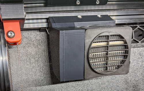

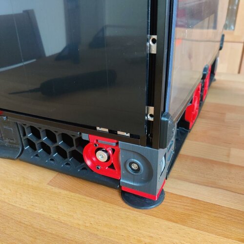

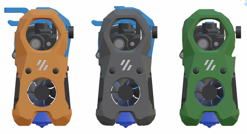
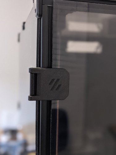
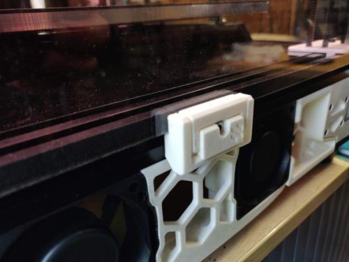

.thumb.jpg.455d15673ede3fd647f42b97864bbce2.jpg)