Leaderboard


Popular Content
Showing content with the highest reputation since 03/11/2025 in all areas
-
There's some wonderful new filaments on the block... Fiberon by Polymaker! So far, I've tried two of them... PET-CF17 and PPS-CF10 Both of these filaments are very stiff, temperature resistant and dimensionally stable. They are also considered abrasive filaments, requiring the use of hardened nozzles. Here's my findings: PET-CF17 Fiberon PET-CF17 is a good choice if you have a standard hotend with a conventional Thermistor, rated up to 300C. Prints come out well at 270C though the surface finish wasn't great for me with a 0.6mm nozzle. The filament is quite brittle and needs a gentle filament path with no sharp bends. Warping is absolutely not an issue and prints are dimensionally stable and quite strong. The strength and heat resistance can be improved with post-print annealing at the cost of added brittleness. Like most filaments, PET-CF17 will burn if ignited.... it does not self extinguish either. This is not a cheap filament, going for about twice that of common filaments. (currently about $25usd for 500grams) PPS-CF10 Fiberon PPS-CF10 is a great choice if you have a high temperature hotend with thermistor / thermocouple / what have you/ rated to at least 350c. I upgraded to Revo High Temperature PT1000 which is rated to 400C. As with the PET-CF17, the surface finish was poor at 0.6 but pretty decent at 0.4 with a tiny bit of stringing.... perhaps some settings changes might help. Again the filament is brittle and easily snapped, maybe slightly less so than PET-CF17. Again, absolutely no warping and parts are dimensionally stable and quite strong. Post-print annealing can improve strength and temperature resistance (to 250C!). Breaking a part does not seem to favor layer lines when printed at 330C . If you drop a part, it sounds metallic! And, here is why it is my new favorite: This stuff does not ignite! I cannot get it to even start burning a little with an open flame... it just melts and smokes a bit. PPS-CF10 is very strong, has great layer adhesion, great dimensional stability, very high temperature and chemical resistance and all for the low, low cost of roughly quintuple that of common filaments! (currently about $70usd for 500grams). Sign me up for more because I cannot conceive of printing ANYTHING to do with a 3D printer Hotend or any structural part inside of an enclosed printer out of anything else at all. Printed parts do seem a bit lighter than ABS parts though I have no direct comparisons handy... yet. Comparisons are upcoming as I'm currently printing out Stealthburner Printhead parts. Because I was curious, I tested PPS-CF10 for electrical conductivity, and it does not conduct even when measured with a capacitor leakage tester rated to 1.6GΩ @27v, (that's 1.6 Giga ohms!) as opposed to a standard ohmmeter's range of 50MΩ at maybe 9v, which likewise reads "infinite" resistance. Happy Printing!5 points
-
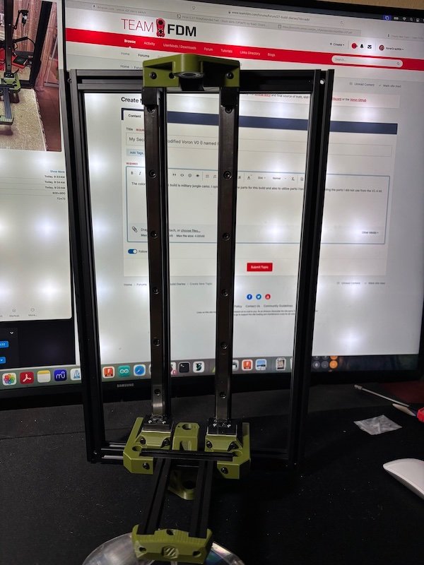
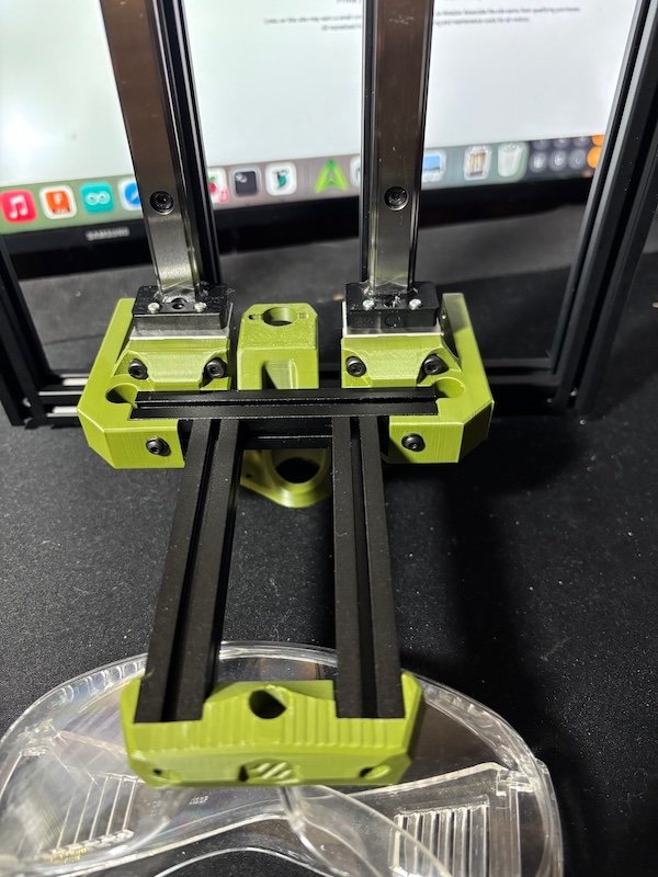
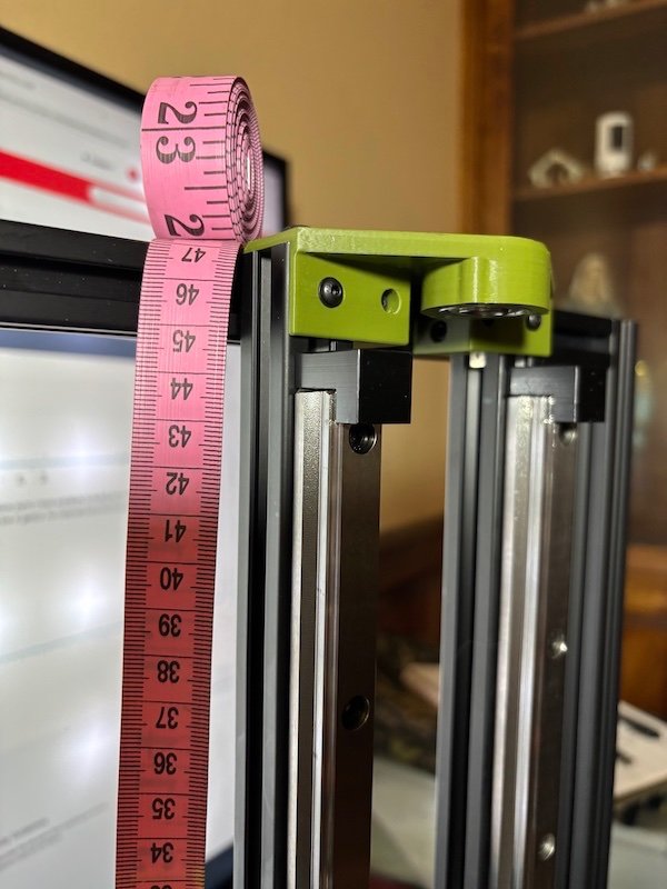
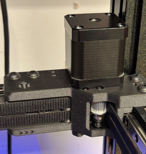
The color scheme for this build is military jungle camo. I opted to source the parts for this build and also to utilize parts I have available including the parts I did not use from the V2.4 kit. I used 2020 for the frame to accommodate the 15mm THK rail and standard 1515 for the build plate mount and the X gantry. As I learned from the first build (Mods as I go), I am now just printing parts as I need them so I can make modifications as needed or desired. This V0 frame is 470mm tall without the hat and 270mm wide. TR8x8 lead screw and coupling to the motor. The weight of the Z with the HSR15 bearings really makes it heavy but at the same time makes me even more curious if it would work Hmmm... I have some new Nema 17 motors on hand (StepperOnline 45Ncm 12-24V) so I will try them first and see. My question is what board can I use that can accommodate 3A (for LDO 42STH48-2504AH just in case) but small enough to fit the V0. Thanks in advance for your inputs.
 5 points
 -
I forgot to add. The older I get the faster I was5 points
-
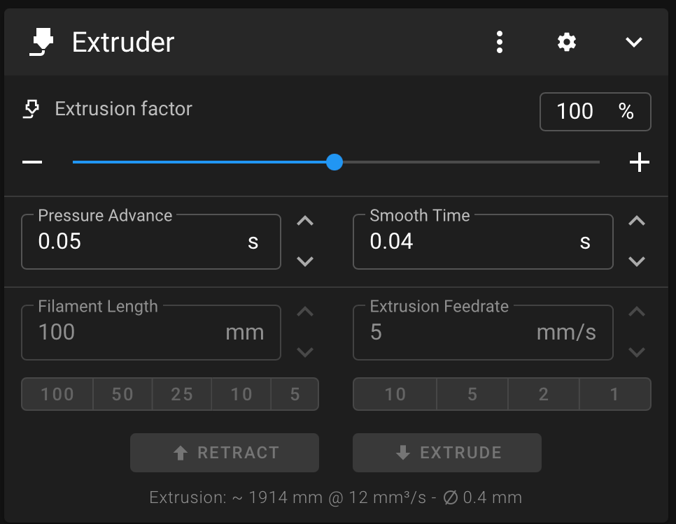
Thank you, everyone, for the reply. It turns out the pressure advance in the filament section in Orca got unchecked. The 0.05 was what I was seeing in the Klipper Extruder IU section, which is the default from the Klipper setup. All prints are back to normal.
5 points
-
Retired mechanic looking to hang onto the skills learned over 30+ years. Always enjoyed the diagnostic part - - once you know *what* is wrong, fixing it becomes the easy part! 3D printing is definitely exercising those skills! I've had to learn several new ones as well, starting with CAD (using mainly FreeCAD), "programming" of sorts in learning how to flash new firmware, then dumping that as too troublesome and shifting to Klipper and an entirely different set of issues! Like it a lot better than Marlin, though! Machine started as an Ender 3, quickly started changing things: quieter board (SKR mini E3 v 3, after toasting a v2), dumping all the noisy fans in favor of Noctua silent fans (and adding a dedicated 12V power supply to run them), adding a second Z stepper, trying various configurations of direct drive and hot end setups, most of which has issues with heat creep. Last outing was a HeroME setup with dual 5015 print fans and a V6 hot end, which worked well enough but really didn't meet expectations. Had Voron envy almost from day one (I'll get there one day!), and got parts for the Voron Stealthburner print head, retaining the V6 hot end for now. Added a linear rail to the X-gantry. Added drag chains for the bed, the X/Z gantry, and eventually the X/printhead as well. Didn't print them, just bought 'em from 'zon. Did print the "anchors" for the chains, first thing I ever used CAD for. Went for the "barf" LED lighting for it (beneath the Voron logo). kept the V6 but added a PT1000 thermistor. Not running YET but I'm knocking down issues as fast as I can find them (often with input from here!) Finding good information isn't always easy, and I've found that this site is one I can count on for good, accurate, and *complete* information, which is more than I can say for many, and has become one of my top "goto" sites. I appreciate your being here, and am happy to be a member!5 points
-
Received the serial number for this build yesterday.... This build I suppose is now officially over.. but tuning and mods will be never-ending ha ha.. On to the Next...5 points
-
One last mod to finish up the project. Clicky-Clacky Door Mod. And... The printer is now in my office and printing beautifully. Printed parts... These were printed on my VzBot. Material Polymaker ABS Black, 5 perimeters, 5 top, 5 bottom and 30% cubic infill, no supports, no brim. Bed 110, HE 240, Outer walls and top surfaces 200mm/s 5K accel. All other walls infill etc. 250mm/s 10K accel. Travel = 800mm/s 20K accel. Print time = <3hrs I put all this print info up here because I'm curious to see how fast others are printing ABS. And of course, the quality is not bad.
4 points
-
Just announced on discord and posted to printables. Yet another mmu. These guys have got to stop tempting me to build things! Link to HTLF4 points
-
Welcome, I just stumbled on this community and I seemed to fit in. It's an easy going relatively ego free place - we do have a weakness for motorcycles (my doctor calls the Donorcycles) and, possibly, cats.4 points
-
You guys really suck, Ya know... Clicky-Clack door on order. Might as well finish up my refurb with a nice mod. I also ordered new top and side panels. The old ones had heat related fogging that couldn't be clean away. They're fine actually but for ~$40 I'm getting new ones.4 points
-
From the above it looks like it has flashed "File download successful" The last error is common an can be ignored "Error during download get status" The device will not show up as a USB device any longer as it is now a CAN device with catapult on it. Make sure your can network is up and running. sudo nano /etc/network/interfaces.d/can0 enter this into the file: allow-hotplug can0 iface can0 can static bitrate 1000000 up ifconfig $IFACE txqueuelen 1024 Save, and shutdown everything. Restart the pi, query the can network: ip a and make sure you see the can interface: can0: <NOARP,UP,LOWER_UP,ECHO> mtu 16 qdisc pfifo_fast state UP mode DEFAULT group default qlen 1024 link/can promiscuity 0 minmtu 0 maxmtu 0 can state ERROR-ACTIVE restart-ms 0 bitrate 1000000 sample-point 0.750 tq 62 prop-seg 5 phase-seg1 6 phase-seg2 4 sjw 1 gs_usb: tseg1 1..16 tseg2 1..8 sjw 1..4 brp 1..1024 brp-inc 1 clock 48000000 re-started bus-errors arbit-lost error-warn error-pass bus-off 0 0 0 0 0 0 numtxqueues 1 numrxqueues 1 gso_max_size 65536 gso_max_segs 65535 RX: bytes packets errors dropped overrun mcast 11412 1551 0 0 0 0 TX: bytes packets errors dropped carrier collsns 3568 641 0 0 0 0then get the device UUID: then get your device UUID: python3 ~/katapult/scripts/flashtool.py -i can0 -q write this down and continue to flash klipper to it - see Esoterical Canbus guide:4 points
-
Hello Everyone, Been interested in 3D printing since the days of having to build your own. Never had the time or money to do that. About a year and a half ago I finally decide to buy a printer. Bought a Bambu P1S and l was hooked. A few months later and I had to buy a second, this time an A1 Mini. I have enjoyed them both but still had the itch to build one. That's when I decided to pull the trigger on a Voron. Just received my Formbot Trident 350 kit a week ago. Still mid build and looking forward to all the learning, tinkering and modding in the future. Thanks, Dan4 points
-
I received more aluminum stock and planned on making the double vice, the base for the double vice, and the sliding base for the single vice. However, I had ordered the wrong vice from SWM (1/4" instead of M6), so I have the top vices. Today tramming the mill, installing the new 12V power supply, securing the wiring in the Casa, installing plexi in the doors, and completing the air lines and mist system. @Penatr8tor Hey Pete any update on your Milo?
4 points
-
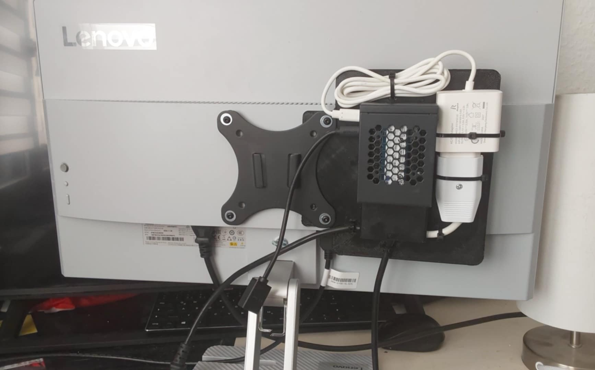
I've been busy. This is my new TV/Computer for my camper. It's a Pi5 with a 1tb nvme, running KDE and Android. It's on a QR mount for safe storage.
4 points
-
I have been running my 2 Voron 2.4, a 300 mm and a 350 mm, for a few years now with excellent results and minor updates/upgrades, like Klicky probe, Release 2 updates, part cooling 5015 fan, Nevermore filter and some cosmetic changes. It is also time to replace some plastic parts, deep clean and grease the linear rails, check belts and pulleys etc. The 300 mm Voron 2.4r2 (aka Voron-1) is running great for about five years now with the above upgrades and minor maintenance, so it was the first one to get an upgrade and maintenance. Stealthburner with LGX Lite v2; originally full size LGX. Reuse the Mosquito hotend with new heater and thermistor, and Convert from conventional cables to CAN network and finally go from Klicky probe to CNC Tap system. After rails serviced, new plastics printed and all the new parts for the Stealthburner, including LEDs, EBB etc. put together, the Voron-1 is back in service and working great! The CNC Tap system works great and love the simplicity of the CAN network; four cables! The cable chains look empty now! So it is time to service and update/upgrade the 350 mm Voron (aka Voron-2). But, I am not too happy with the part cooling performance of the Stealthburner, especialy try to print PLA fast, so I started researching other solutions. Of course, CPAP turbine and hose is the top contender for supplying part cooling air. Then I found the wonderful Github site of sneakytreesnake and his not Voron mainstream head CrownCooler. Unfortunately, is designed for Orbiter with a Rapido head. I have a Mosquito and a LGX Lite V2; so here we go to Fusion360! The existing projects I will be using are: CrownCooler (modified) Voron CPAP with muffler from Flaigenstool Engineering (modified for TPU gaskets) V2.4-Aire from @VoronManiac
3 points
-
Keri, when I tried first "defining" the PT1000 with three resistance/temp values, then declaring that defined thermistor in the configuration, it gave Klipper a fit. Wasn't until I got rid of the definition and declaration, and simply stuck "PT1000" in sensor_type and 2200 for pullup resistor, exactly as midmadn said, that things started working better. Apparently when you try to tell Klipper something it already knows, it gets testy! I can see how that jumper works - - slick way to implement different resistor values for different thermistors! I don't think such strict accuracy is required for quality prints; likely using a PT1000 for printing with plastics is overkill, like using a shotgun to deal with mosquitoes, given that printing temp ranges stated for any given filament are closer to ballpark estimates than to three decimal-place precision figures. I'll forget about the precision and just take advantage of the greater range. Yeah.... this is exactly the kind of rabbit-hole I'm far too prone to get sucked into! I get caught up in the technical side of it and forget about the 'diminishing returns' aspect. It's great fun when you finally figure things out and everything works, but if it makes no practical difference in the end, it's just for fun (or "funstration," as my partner-in-crime likes to call it, given the dearth of accurate and *complete* information.) I think consumer/hobbyist-level 3D printing is still in the "wild-west' stage, much like phonographs were back in the day, when each manufacturer did their own thing, records played at different speeds for different makers, etc - - took quite some time for any industry-wide standards to become established. Still, this printer is serving it's purpose; I spent three decades learning to troubleshoot and repair some fairly complex equipment, and hated the thought of losing those hard-won skills in retirement. For me it's more about tinkering with the technology than actually printing useable and/or fun stuff.3 points
-
I'm running sensorless, so no Y stop switch. I've got 4 motor wires in an umbilical from the centre of the gantry down to the hole in the baseplate.3 points
-
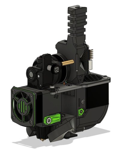
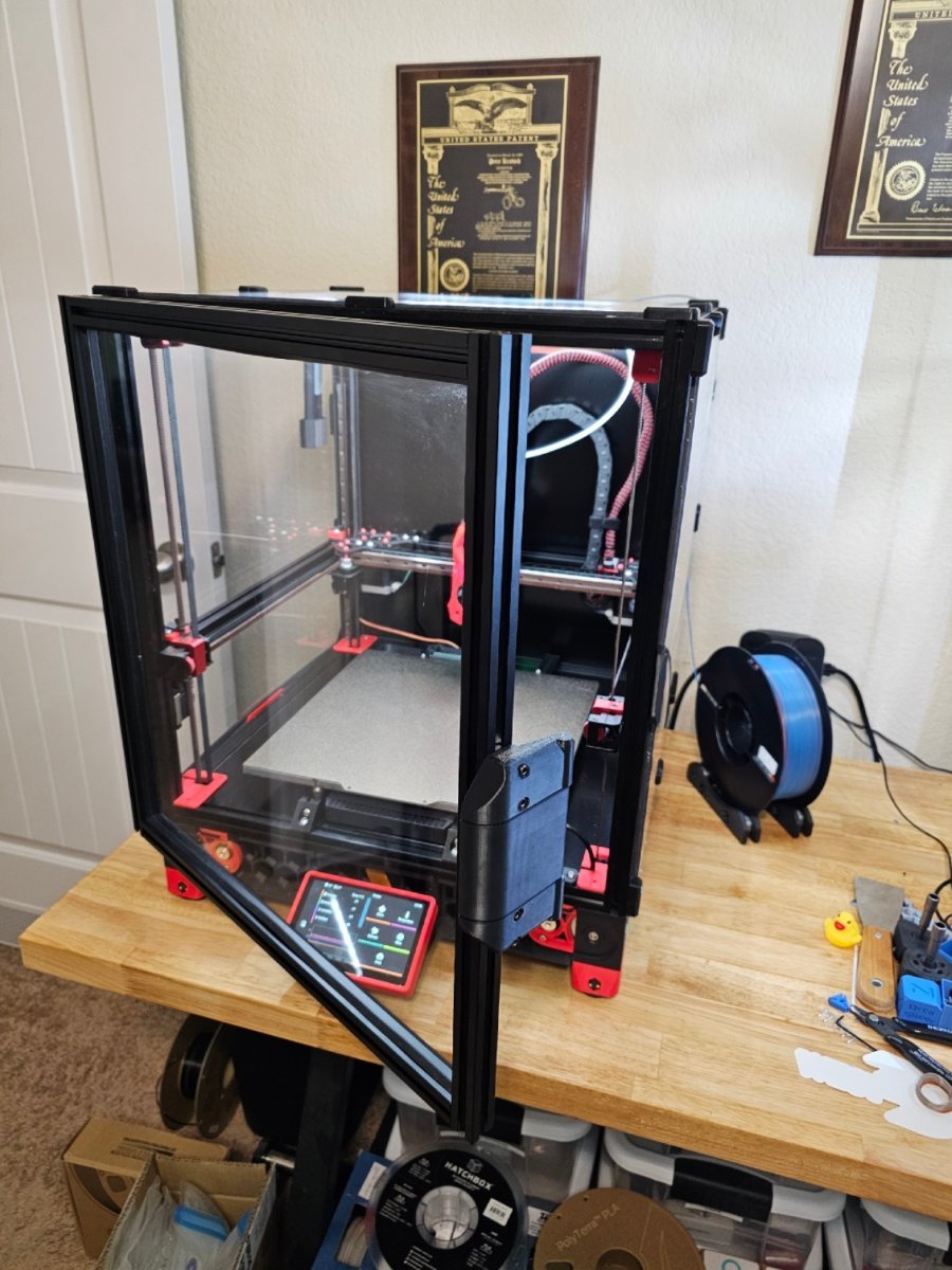
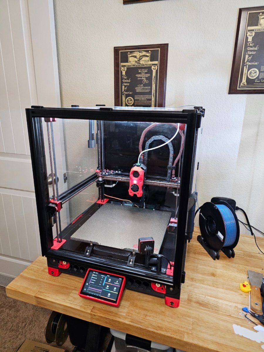
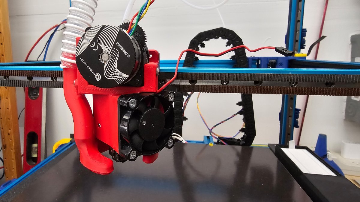
Functional head completed and ready to test. Some stats: Extrusion nozzle to linear rail carriage 28 mm (Stealth 28.10 mm) Overall width 84.966 mm (Stealth 85.216) Height from nozzle to Extruder lever 105.357 mm (Stealth 145.063 mm). 3 printed parts for everything; no cosmetic or LED/camera mounts yet! Need to add the EBB36 CAN holding frame and wire everything before for 1st run. Some images: It's amazing how "clean" it looks with the 2 wire chains gone! Hopefully, it actually works too! Cheers!
3 points
-
It's been a while! Been busy with stuff. But through it all, the Voron 2.4 has been working well. However, I've never really liked Voron TAP all that much, though it does actually work fairly well across a variety of build surfaces. To be fair to TAP, it has worked better than anything else I've tried. The MellowFly CNC TAP has been a great experience.... it works consistently well, with only a little maintenance needed after quite a long period of use. But what if there was a way to achieve the same result for probing without the weight and rigidity characteristics of TAP? Klicky and various touch type probes are already well developed but E3D has just come out with a new and exciting (what could go wrong?) Piezo electric probe built into a Revo Voron Coldside, The Revo PZ Probe Voron. They've been out of stock for quite some time but are now available. So, I ordered one and it arrived in a week or so. The kit consists of a special Coldside Heatsink with an integral Piezo sensor, a dedicated circuit board, a 1.5m long harness for the circuit board, and inexplicably, harnesses for the heater and thermistor wiring. There are no Hotend or Nozzle parts included, nor any instructions. There's a custom X-carriage to download and print with mounting holes for the circuit board and that's about it if your systems already set up for a Revo, as mine is. The following are my initial impressions: So, off with the toolhead, off with the (Mellow CNC) TAP, on with the X-carriage, the circuit board and the Revo PZ heatsink. Some changes to printer.cfg and ready to go, right? Maybe not so much. E3D's online instructions are a bit sparse but there is an instructional video on YouTube from E3D. Eventually, I got everything installed and configured, though the road was a bit bumpy. Bump #1 - The Revo PZ is a 3.3 to 5 volt ONLY part. So, using my MellowFly SB2040 CANBUS toolhead's 24v probe connector, gpio25, was out of the question. Fortunately, there is a 5 volt endstop port right next to it, gpio28. But, plugging the Revo PZ into this port crashed the toolhead! Oh. It seems MellowFly built a board with a 5 volt port that cannot tolerate 5 volts on the sense pin, which can only tolerate 3.3 volts. It seems that the Revo PZ's board output is apparently NOT "Open Collector" and toggles between 5 volts and 0 volts when triggered. Now, where was that BAT85 diode again? OK, it works with a BAT85 diode installed on the sense wire, (band towards PZ board), kind of what is needed when using certain inductive probes. Not E3D's fault, but a heads-up would have been nice. An included BAT85 would have been nicer yet. Bump #2- The Revo PZ is quite touchy and sensitive, so even though E3D's recommended printer.cfg changes reduce the likelihood of false triggers during probing, they can still happen. For me, Quad Gantry Leveling would cause false triggers. There is a button on the PZ control board to choose between sensitivity settings, but I found that dropping the QGL speed to 80 stopped the false triggers. Advice is given on this, but it isn't that easy to find. Bump #3- the consistency is not as good as traditional TAP. The initial testing of PROBE_ACCURACY is all over the place. It might return a great result of 0.005 range/0,001 standard deviation or as bad as 0.03 range/0.010 standard deviation. As nothing was altered between subsequent tests, it is likely the characteristics of the piezo sensor. Perhaps changing the sensitivity setting on the Revo PZ control board might help. For now, I changed QGL's tolerance and retries settings. Other stuff that isn't exactly bumps... 1- The Piezo sensor has a thin and narrow flat flex cable that leads to the Revo PZ control board. It is relatively short and quite fragile. Short is good for signal integrity and not getting tangled and flopping about, but is isn't much fun to work around and impossible to fix if damaged. 2- The wiring for the PZ control board is a pain because E3D decided to make the board very small but yet offer different interfaces, requiring 8 wires. This necessitates a TINY JST SH connector with 1.0mm pin spacing. this is very fiddly to work with and difficult to crimp terminals for adequately. It would have been nice if two different boards were made available.... endstop type and data type, each with only the relevant wires. 3- Piezoelectric sensors only produce output when motion is occurring, which means the output will only be a pulse of a specific duration, probably set by the PZ control board. If for whatever reason the pulse is not read by Klipper, the Z drive(s) will merrily continue to try and stuff the nozzle through the bed. And now the good news: The toolhead is now indeed extremely rigid and roughly 35 grams lighter than it was with TAP. This has given me my best-yet SHAPER_CALIBRATE charts! All in all, I like it. I think that it will be quite a challenge to get it working as consistently as Mellow CNC TAP but I want to stick with nozzle touch probing and this is the only way I've found so far that doesn't involve significant extra weight and / or loss of rigidity. I would prefer some kind of strain gauge arrangement rather than a piezo sensor but PZ is what I have on hand so.... Happy Printing!
3 points
-
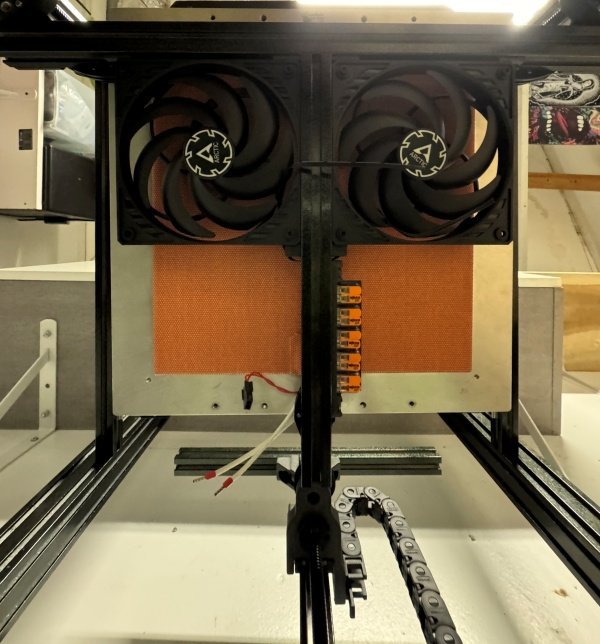
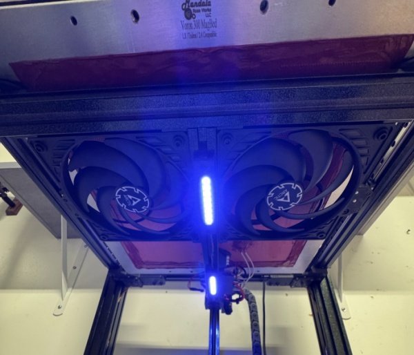
Ill never get through this if i log my actual thought process and steps, so ill keep it shorter as much as possible. Im stuck waiting on parts for the gantry so jumped to the toolhead to get it done, this wont be the actual toolhead when the build is further along since the final one isnt released yet and will be the toolhead that will really change things, its all hush hush at the moment but its coming. toolhead A4T by Tas at Armchair Engineering Board - LDO nitehawk 36 (temporary for setup and dialing in printer) Hotend - Phaetus dragon ace volcano CHCB series w/ 100watt heater cartridge Nozzle - only west3d undertakers, theres no reason to ever run anything else and they last forever so a real no brainer. Fans - Always Deltas when i counts. Extruder - WWBMG Filament - 3dxtech ezPCCF About this toolhead, Tas did a great job on designing this one, its a really nice build and fairly easy even with finicky plastic to print, if you need a new one or want to replace your dated SB for something with decent cooling and a really broad compatibility list of hotends and extruders give this a try. I really like the nitehawk board and would keep it if it played well out in the heat but I dont think its gonna like the chamber temps north of 70c once im paneled and insulated but for setup you cant beat it, so much easier than CANbus but back to straight umbilical ill be going in the near future. Installed the bed fans as well, I decided to try a new approach rather than the usual 4 5015s, these are Artic 120mm 12v hardware controlled pwm fans, I made up a little splitter for the connections as well but havent got it done yet, these fans are silent, super low profile and move a ton of air. Started wiring, really close to powering it up now. Parts finally arrived for the next step. Gantry - Monolith 2wd 9mm belts Steppers - steppersonline 17hs19-2504s-h-v1 2.5amp Pulleys - genuine Gates Bearings - West3d berzerker flanged 695 Belts - Gates G2 EPDM 9mm This took some time to complete, there is no manual or setup guide just a configuration generator and a bom the rest is on you. What I will say about this and with building . vorons in general is if you actually are reading this and trying to figure out how to build a really good printer or just building your first Voron, Discord is your friend , and the amount of knowledge there is staggering if you know where to look. If you want a bunch of nonsense and horrible advice from overnight experts than by all means ask your question on facebook or reddit but you will get mostly bad advice, answers or criticisms on parts of your photo for items you arent even asking about and typical nonsense or drop into the voron discord and open a help ticket and get your problem solved by people who really know whats up, for me its always some little mistake in the cfg that will take seconds to diagnose. If I didnt have Discord for help I would never have finished this build and if i did finish it wouldnt run nearly as well as its about to soon. Helpful Places if your stuck or just need advice. obviously discord, channels - Armchair Heavy Industries Monolith Doomcube VoronDesign West3dprinting Parts for monolith need to be incredibly strong due to the extreme belt tension so again i used the pccf with 12 walls and 12 top and bottom , I spent a good amount of time making sure the filament was tuned perfectly or as good as i could anyway so that my tolerances were spot on. I also decided to go 2wd instead of AWD for now , im in pretty much over my head on this build and dealing with AWD just seemed to be to much but I do plan on upgrading as soon as wayne releases the cnc kits for monolith. Starting to look like a printer now. I also added a couple neopixel strips under the bed to light up the electronics bay when i need to see. After the usual headaches writing the config and a few help tickets pulled in the voron discord and triple checking my wiring I did the ole hold your breath and push the button, no magic smoke, lights cam on and it homed, well it homed backwards and changing the dir pin didnt fix it because after all my checking I still got the x and y steppers swapped somehow, easy fix and it started to home and stopped immediately as expected before tuning the sensorless homing, if you dont run sensorless I can only stare blankly and ask why? I havent had an endstop on a printer in a few years and will never as long as the drivers support it, just makes life easier. It lives. It homed, and it printed a quick voron cube very nicely and then I started thinking. Something was missing.
3 points
-
Many, many thanks @TitusADuxass! That's what I was looking for! Size matters when it comes to sound! I have not tried the VZbot intake muffler yet, but I thought it was too small of a sound chamber to do any significant reduction. Anyway, I needed something to start, and many other solutions are using external air which will be great for PLA but not good for ABS, ASA etc. Eventually, I need to find/make a solution that uses a baffle that automatically draws the correct air for the filament used. The only other "muffler" I have found CPAP Muffler System - C.M.S that it had potential but I needed something quick because I am working on the completely new head and needed a quick print tot test it. The designer of the CMS muffler had some good points and I will try eventually: Enclose the turbine housing in a sound deadening material. "Soft" mount the turbine as I am sure is not balanced at high RPMs.... Cheers!3 points
-
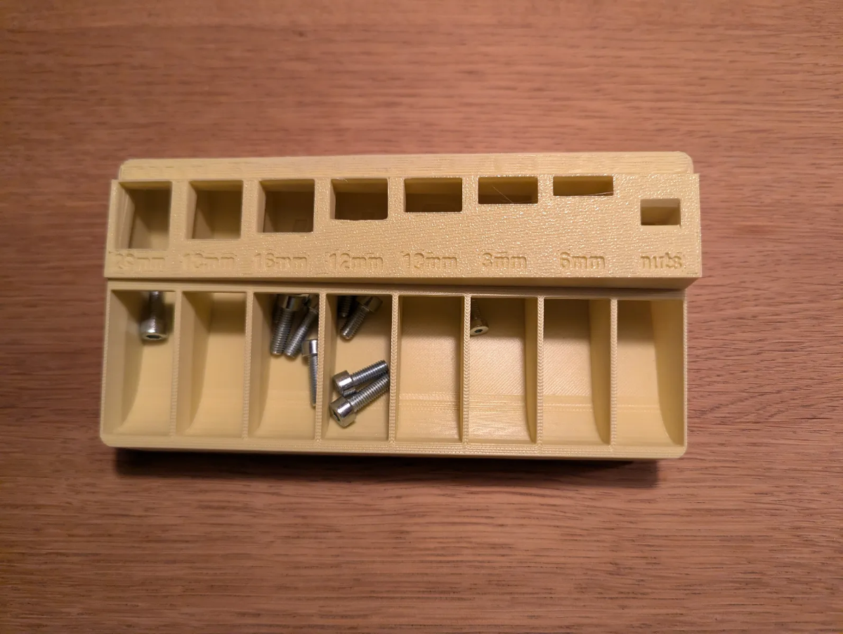
Not a Voron item but a handy item to have on hand. Printed this m3Sorter_bottom_gridfinity.stl for the top to fit. https://www.printables.com/model/874548-amazing-gridfinity-m3-bolt-sorter And this one for a greater assortment of bolt sizes. https://www.printables.com/model/993430-gridfinity-m3-m4-m5-m6-mx-bolt-sorter
3 points
-
I've been using it for a few of my main filaments. It does improve the first layer. I often had pinholes between walls and infill on the first layer when using a constant PA value. Beyond that, I don't really notice much difference. Calibration is time-consuming. It's not too different from a regular PA test, but you have to do it at least 12 times under different conditions, then use a spreadsheet to prep the parameter block. There's a batch mode that sets up multiple calibrations, but each test area is just a standard PA calibration print. Overall I think there's something useful here, but I suspect that the model doesn't really need to be so complex. There are clear patterns in the test results that I don't think the current model takes any account of. (It seems to just be doing separate interpolations along two different axes.) I would bet that if we could collect enough calibration data, the model could be simplified to the point where it would only require three or four test prints. It wouldn't be as accurate as the current model, but I bet it would reach the 80% mark.3 points
-
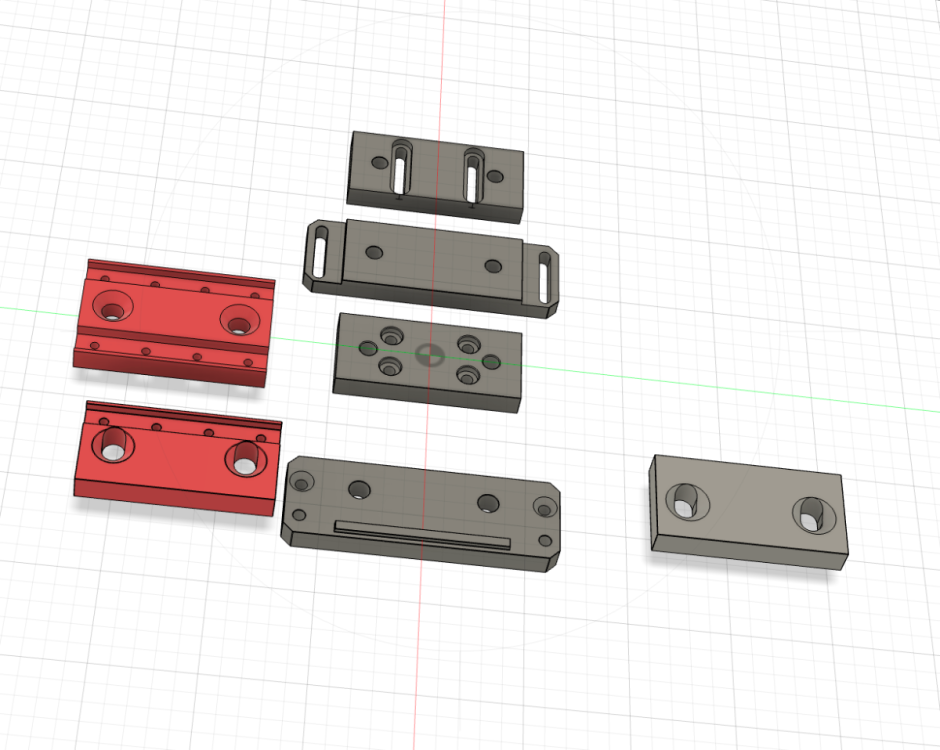
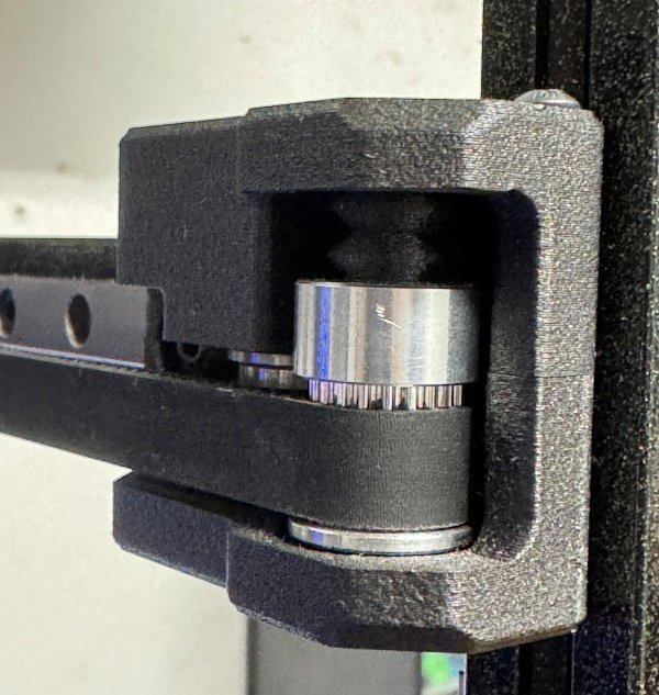
Just in case someone want to experiment, here's the Modified bed mount stl for THK HSR15. The bed plate extrusion and mounting specs are maintained. Z Motor Lead Screw Bearing Mount.stlRear Bed Mount Right (Modified).stlRear Bed Mount Left (Modified).stlZ Motor Mount.stlZ Endstop Mount (modifies).stlLead Screw Bearing Cap.stl3 points
-
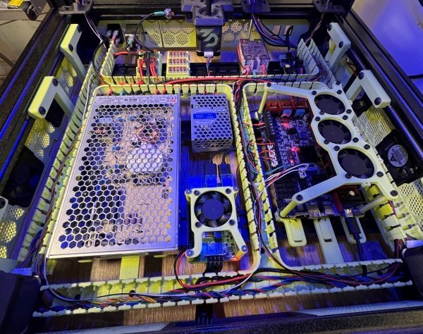
Finished up the skirts which took some work, the doomcube stl files on the github are not modeled for a 300mm machine, theres 250 and 350 and theres two different front styles depending on the door cfg. The old ones left the skirts back 20mm like if you have added a clicky clack door on your machine and havent redone the skirts. I luckily found a complete cad file for the entire machine that included the new front skirts with the additional 20mm ledge and was able to hack my way thru with fusion to make them the right size for my machine. Electronics up next. So i decided to remodel the layout of the electronics bay that Voron uses and almost everyone else, as well as use the inverted electronics bay mod, honestly it shouldn’t be a mod and should be adopted as how it should be done since it makes everything easier down the road. I wanted this build clean and tidy with very little wire showing as well as mounting the electronics perpendicular to the din rails rather than parallel and divide everthing like a tv dinner, each item has its own place. I also flipped the build plate drag chain to the opposite side, because i can and because the layout lends itself to wires running up the right side rather than left. Rails greased and installed, Berserker mgn9s from West3d, as well as titanium backers. Motors for zed are LDO 300mm steppers with teflon coated lead screws along with the spacer mod to drop the end of the the leadscrews like 12mm, I did this on my trident in order to run the mjolnir toolhead from armchair engineering but for this its 100% for vanity, it just looks better. The z linear rails are mgn12h rather than the usual mgn9, yes it looks beefier and no it is not needed but I had rails lying around so why not save a buck or two. The build plate is the Mandala Roseworks superflat magbed, this was also lying in my ridiculous pile of spare parts due to its unwillingness to play nicely with beacon, I took it off my Trident but wasnt about to buy another plate again even though this build was going to run beacon as well. I honestly have no idea why anyone doesnt run beacon or even the carto but to each their own, I will never build another printer that doesn’t unless something new comes out that’s better. To utilize the build plate I came up with the idea to print some inserts the same dimensions as the magnets in the plate to begin with and cover them with a magnetic sheet, I used PC which I hope holds up to the heat planned but for now it worked perfect and a chunck of cash saved. Electronics Meanwell LRS-200-24 Raspberry pi 4b Octopus Pro f446 1.1 btt 2209 drivers Meanwell LRS 25-5 Since im writing this in the future several things are going to change before we get current but i will write to match the photos I had a different plan for the voltage and drivers up to this point but decided to stick with what i knew rather than have to figure out 48v and 5160 drivers and the setup associated with going that route. I have only built one other trident before this several years ago and though ive modded it to death I really dont have the technical knowledge to do some of the more exotic mods so I opted for the easier safer route so i could actually finish this someday. I designed the mounting system for the wire channels and modified the cad for the wire channels themselves so that it would all fit nicely as well as Frankensteining all the electronic mounts since nothing really fit, of course i would have done a few things differently now but I think it came out ok and besides it will give me something to change later .
3 points
-
My first Chaoticlab (v1) failed after about one year (after a hard knock). I purchased the v2, and it's been running ever since. The chamber has reached 70C, and based on my printing history, the printer has done at least 2500 hours of printing since then. Still works fantastic, perfect first layer every time. My newly built Trident has a CNC Beacon mount and a Beacon probe. It's working well, but I did have issues with first-layer inconsistency. I think that's because filament on the nozzle will not get pushed out of the way like a TAP. So, a nozzle scrub is 100% required. So it needs a macro which does G28, nozzle to 150C, nozzle clean and a G28 Z3 points
-
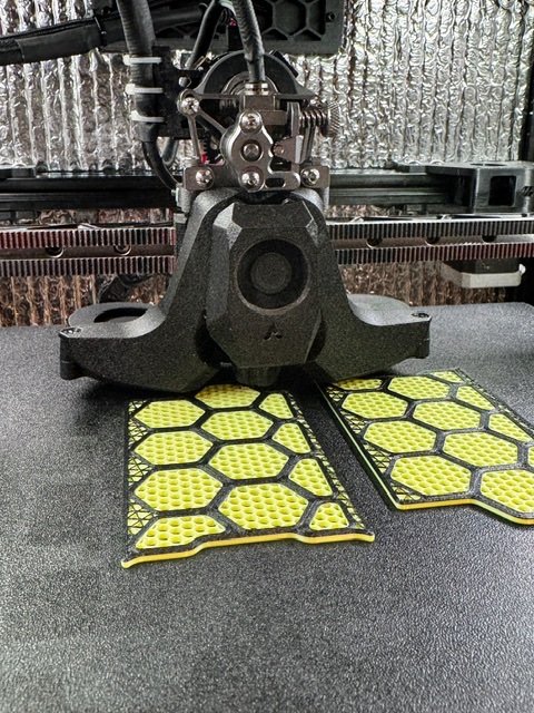
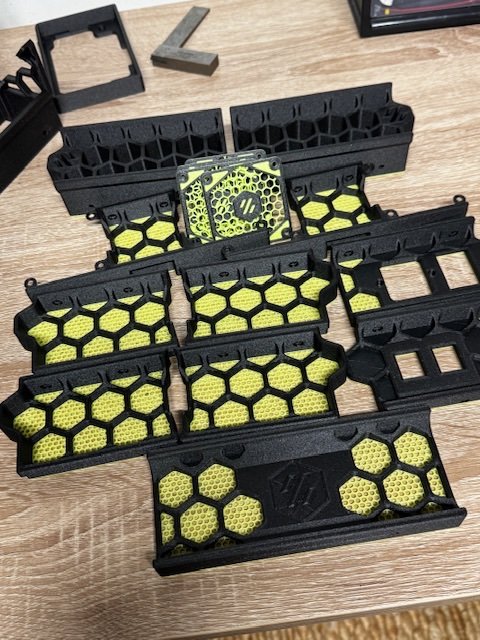
Everything was printed on my Trident which made life so much easier than the first time I did this with a pos printer covered by a cardboard box , no idea how I got useable parts outta that thing but this time it was push a button and walk away. Internal parts completely PCCF, voron print standards with the exception of the gantry parts but we will get to that later. External parts phaetus black ABS-gf and hatchbox pastel green ABS
3 points
-
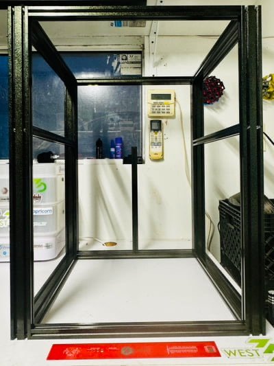
Frame - x545 x y545 x z760 Build volume - 300x300x300 2020, 2040 and 4040 extrusions machined by dllpdf mfg and powder coated in ground up fairie wings. The extrusions took quite awhile to receive due to high demand on a small company , they make really nice stuff so it was worth the wait.
3 points
-
Update: The Revo PZ Probe was not the source of inconsistent Quad Gantry Leveling! It was merely the Z0 belt had loosened slightly... it seems my CNC Z belt tensioners have no means to positively lock the adjustment and the Loctite threadlocking compound didn't hold up on Z0. I did change the PZ Probe sensitivity from the default setting 0 (level 5) to setting 1 (level 10) which reduced false triggers. With all the belts evenly tensioned, QGL now completes much more quickly It has even done a Zero Retries QGL once or twice. So far, I'm liking the Revo PZ on Stealthburner. PS. For anyone wondering about my earlier mention of the BAT85 diode; Certain electronic inputs have a maximum voltage. My toolboard of choice, the Mellow SB2040, has an odd powered endstop connector, gpio28, which has a 5 volt supply, but the input of which can only tolerate 3.3v. With many devices, an "open collector" topography is used, and the toolboard input sees either a 0 volt "grounded" signal or a "floating" open circuit similar to just disconnecting the input wire. With many other devices, including the Revo PZ Probe a "source or sink" topography is used, so the toolboard input sees either a 0 volt "grounded" signal or the full voltage of the power supply to the device, in this case 5 volts. Where this causes problems, one can use a diode, preferably a BAT85, to isolate the toolboard input from the 5 volts "source" signal, effectively providing a "floating" signal thus simulating an "open collector" topography. Happy Printing!3 points
-
Here's my Stealthburner, Orbiter2 with Beacon_H implementation, maybe you can get something from it. As for a Beacon with TAP Project goes... I don't think there is one because getting the probe up and running isn't that tough. Basically, the eddy current sensor detects when the nozzle touches something, and it does it so quickly that the nozzle touches with less that a gram of force. Homing Z: You can home Z using the eddy current sensor or by touching. If you want it to home with touch, you set it to contact in your printer.cfg [beacon] home_method: contact home_method_when_homed: proximity home_autocalibrate: unhomed And proximity if you don't Z Calibration: You can calibrate using the old tried and true paper method or you can use beacon_auto_calibrate and in under a minute... it's calibrated, regardless of whether you switch to a different build plate or temps, etc. it's always perfect. In fact, In my print_start macro... I heat the bed to the printing temp and the nozzle to 150c (heat makes everything expand) I probe, QGL and scan and right before I park the head to heat up the nozzle to printing temp I have... G28 Z METHOD=CONTACT CALIBRATE=1 This tells the printer to re-home Z using the contact method and include beacon_auto_calibrate. That means every print no matter how hot the bed is, the nozzle is calibrated to the bed at the set temperature. So, good choice on the beacon. A beacon and a good setup will make your printer as set and forget as a Bambu labs printer.3 points
-
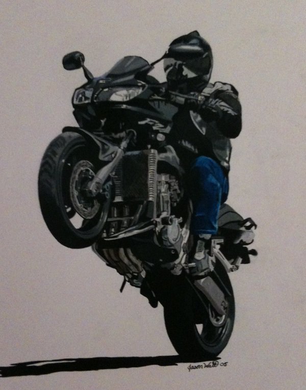
Well... I have two current beasts, one can and the other can't. Below is an original mixed media piece I commissioned from Jason Watt Here's the photo...
3 points
-
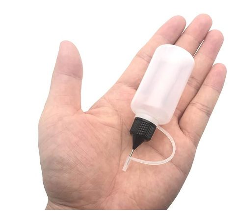
Yup, you assume correctly... All you need to do is stick the tube from you oil bottle. in the groove of the rail and apply a few drops. Capillary action will suck the oil into the groove and when the balls run over the oil it will get distributed. You can just move the toolhead by hand to distribute. And of course, wipe off any excess from the flat surfaces, plus a lite oil coating prevents oxidation/rust. FWIW... My Voron 2.4 just turned 3 years old, and I've easily run 10+ miles of filament thru it. One can only guess how much distance the rail carriages have travelled... All on light gun oil. You can also pick up some of the little bottles on Amazon for cheap.
3 points
-
As the title says... The SuperSlicer people have been working behind the scenes. SuperSlicer Github Video below to get more info... I might give it a try if there's something worth trying.3 points
-
Same here3 points
-
I've never tried it, I've downloaded it but never used it in anger. I moved from Simplify 3D (money grabbing barstools) to Orca. I find Orca overly complicated, but agian I suppose it needs to be. What I do like, and what is missing from other slicers, is the direct interface to the printer(s). I cannot see me moving away from Orca - it did win software of year by the 3D printing industry.3 points
-
Clicky-clacky-CLACK3 points
-
The most awesome IMO was riding the Cherohalla with 4 other riders all on Hayabusa's... There are a series of ~180-200 degree sweeping turns in the middle near the highest point where the speed limit sign entering the corner had 25mph posted... We were all in a tight pack, entering the turn at ~65 and exiting at 120+, a train of 4 roaring beasts, full lean, knee dragging, no fear... just huge grins inside our helmets. Yeah... that was a ride for sure.3 points
-
Deals Gap and the surrounding roads have been a destination of mine for decades. I first went in 2000 with 5 other guys. We rode from Miami to Deals Gap and we brought along camping gear and camped along the way. I had just bought a new 2000 Hayabusa for the trip. I think we logged close to 4K miles (6400km). Since then, I've gone on a trip to that area most years. And my last trip a couple years ago. Time to head back, I think.
3 points
-
Since I reflashed the CB2 I no longer get random communication errors when homing. I've also got PETG dialled in on it, it's now back to fire & forget printing.3 points
-
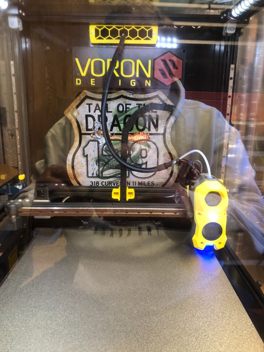
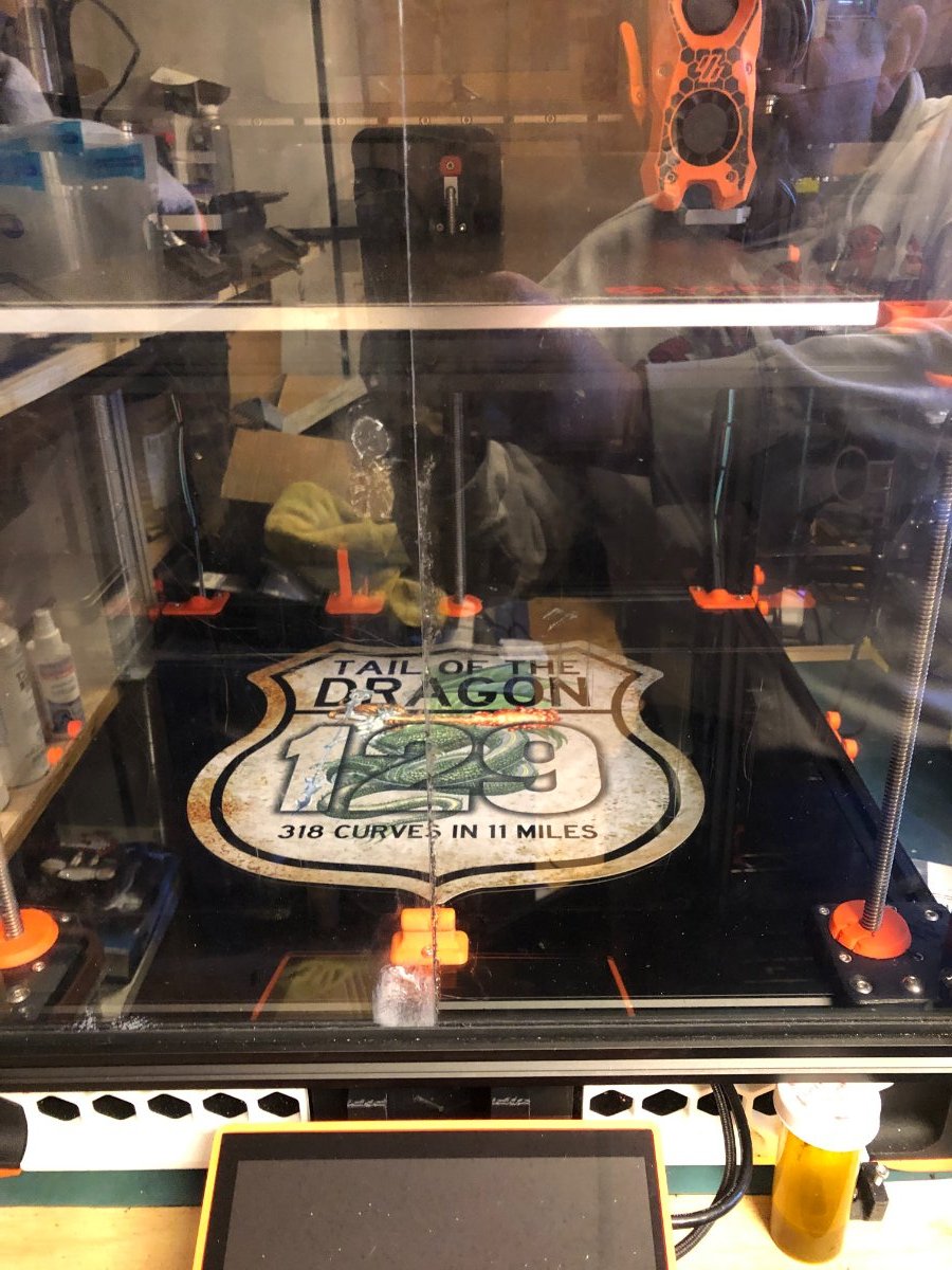
I purchased these signs last year when we travelled to the southern US and drove the Blue Ridge Mountain Parkway and the famous Tail Of The Dragon. I was looking for a home for these two signs and figured the printers would be a good home. For those who aren't familiar with Tail Of The Dragon it is an 11-mile stretch of road with 318 turns it is an awesome feeling to accelerate out of the corner and downshift for the next! Blue Ridge Mountain Parkway is a stretch of twisting 400 miles of road through the scenic mountains and a thrill to drive.
3 points
-
Printer is pretty much done so... Requested my serial number today. Serial Request I have a few things left to do, and I know I probably will be forever upgrading. It has been a fun project.3 points
-
I've noticed the same thing since installing Beacon on my V2, The Beacon probe came in today for the Trident. Well worth the $$ IMO.3 points
-
Version 1.0.0
6 downloads
If you have a RatRig V-Core 3.1 and want to upgrade to the new Toolhead 1.0, you'll need to print the 3 STL's included in the ZIP file. I created these components because the folks at RatRig provided STL's for the V-Core 3.1 but only work with a Pinda probe setup and nothing for the Beacon probe. So, I took V-Core 4 files and modified them to work on a V-Core 3.1. You'll still need to print the belt clips and adjusters along with the CAN mount and replace the Front, Back and Duct parts with mine. These files have been modified to use the RatRig V-Core 3.1 belt system where the belts are tensioned at the toolhead versus the V-Core 4 that tensions the belts at the stepper motor mounts.3 points -
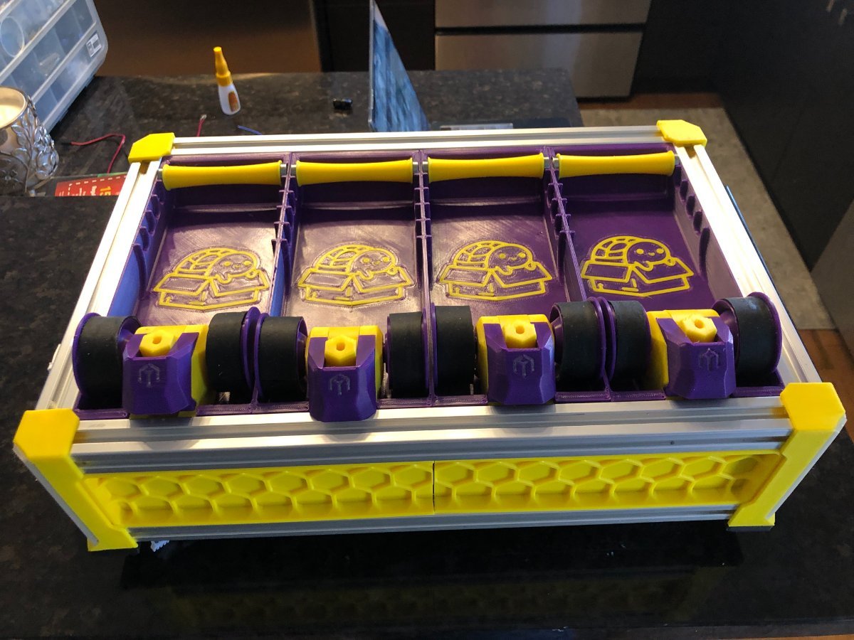
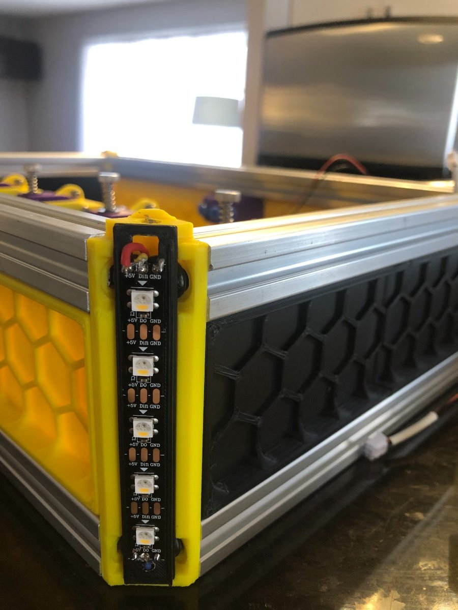
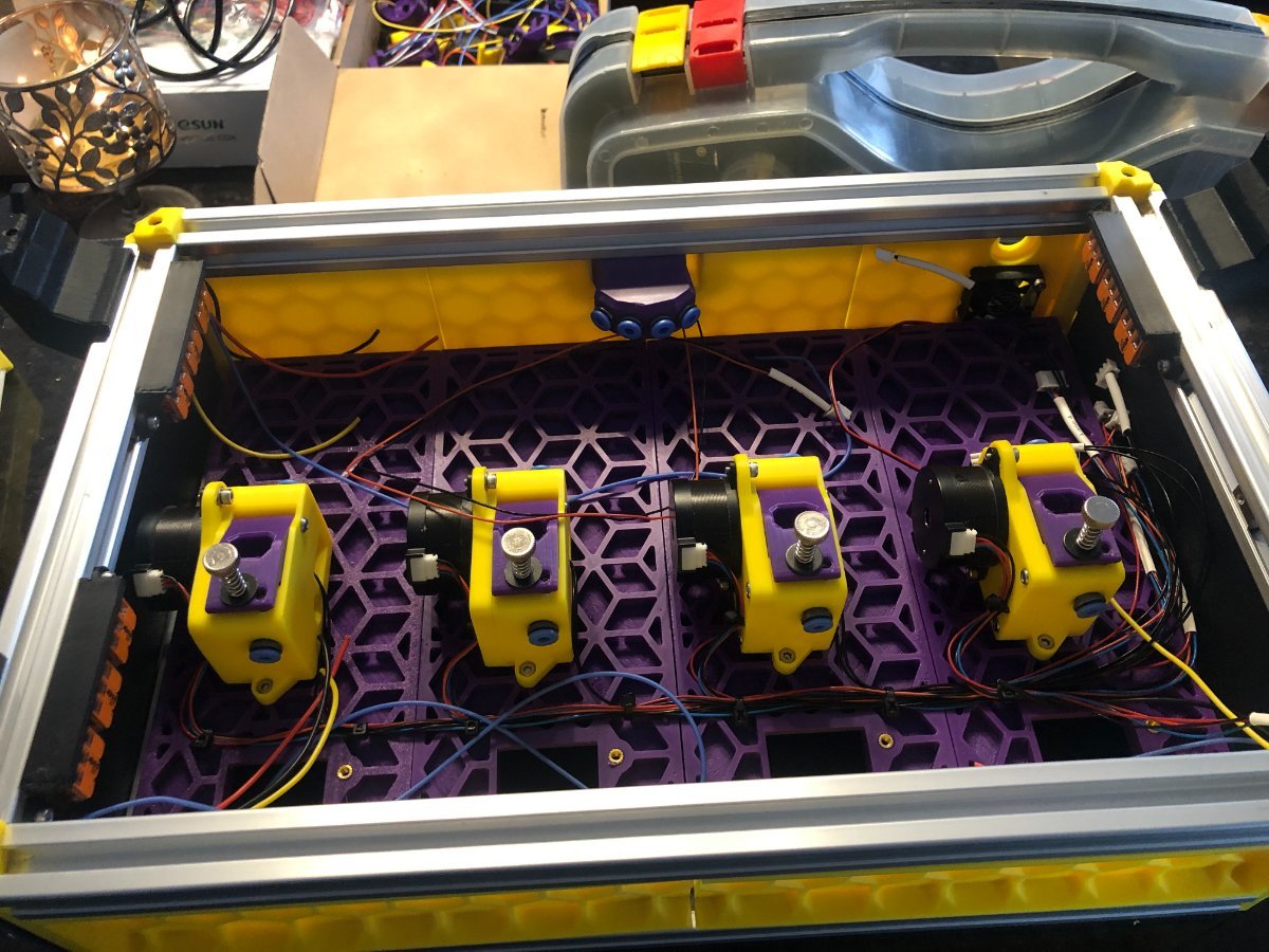
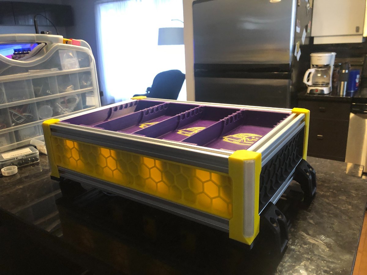
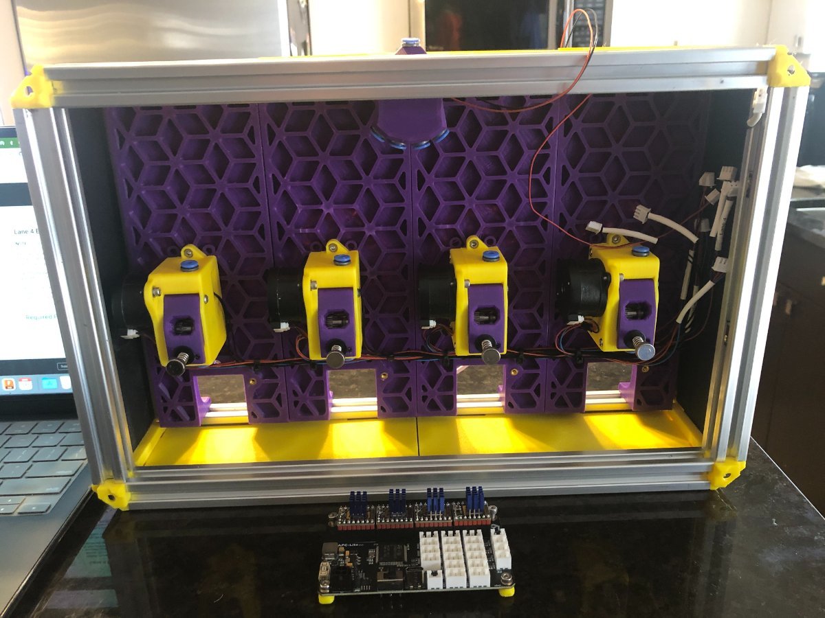
I terminated the wiring for the corner LEDs, and the DC motor came in I assembled and installed the spoolers.
3 points
-
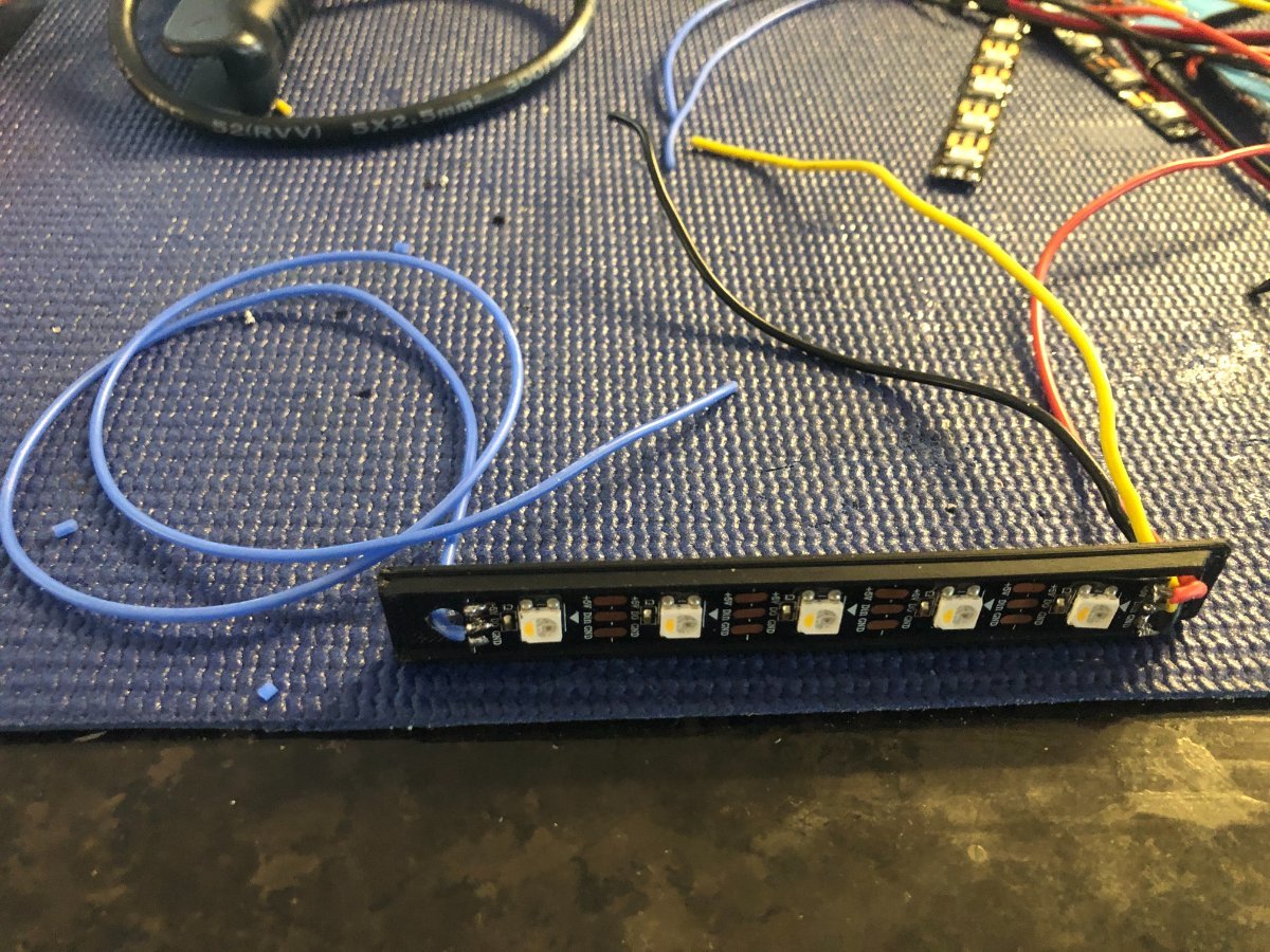
I started installing the corner LEDs today. First, since only the data input and output need to be in series, I drill a hole at the top of the LED's mounting plate to run a wire from the data out back into the underside of the Box Turtle. I'm using Wagos for ease of wiring them. DC motor are schedule to be delivered this coming Tuesday and the missing DF2L.
3 points
-
A bit of progress extruder mounted and got the spooler LEDs soldered and mounted. Still waiting on DC motors to assemble spoolers.
3 points
-
Thanks! I have read a lot of your posts on different mods/tool heads. I must admit you have me second guessing some of my choices & is why I actually became a member and wrote this post3 points
-
Just happy you got it sorted. Never a dull day with this hobby. I rather there be dull days3 points
-
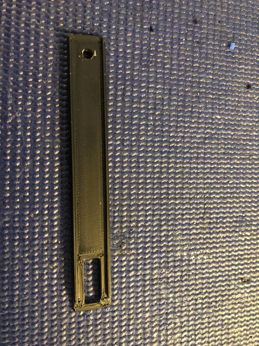
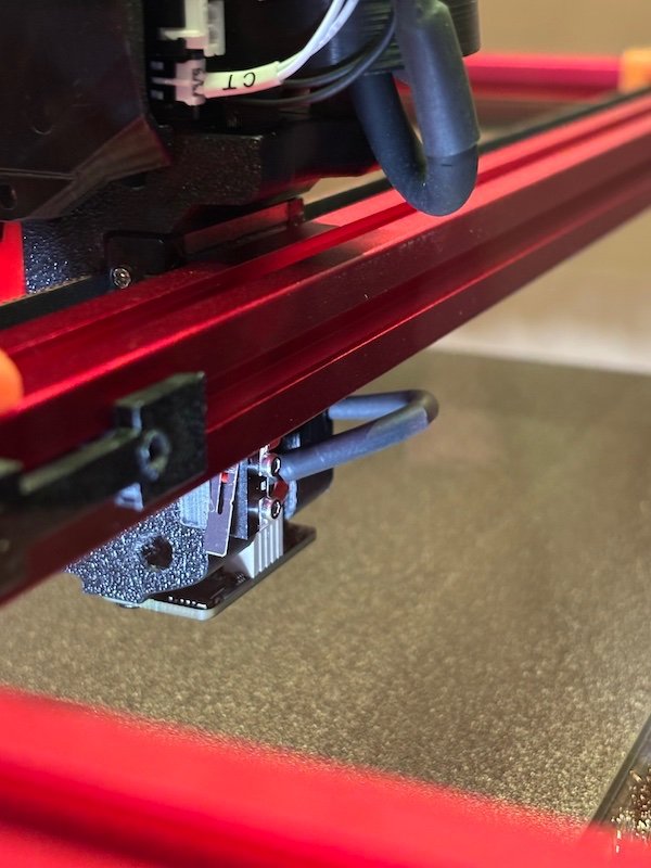
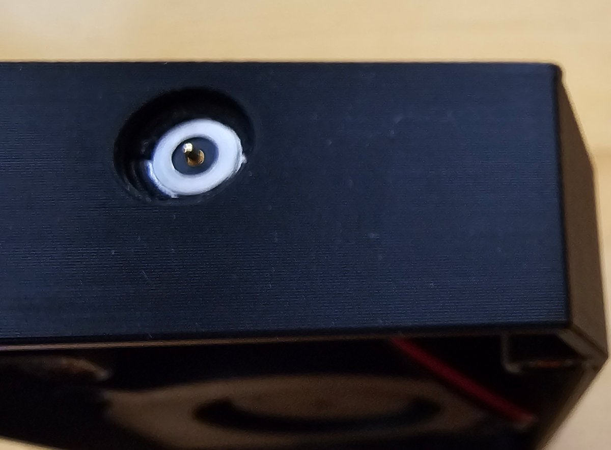
Got the nozzle scrubber configured, lined, and working. I did not want to disturb the gantry so I made a new Y-endstop drop-in mount that is flushed to the motor mount so I can get as much mm as I can. The actuator is mounted on the back rail slot.
3 points
-
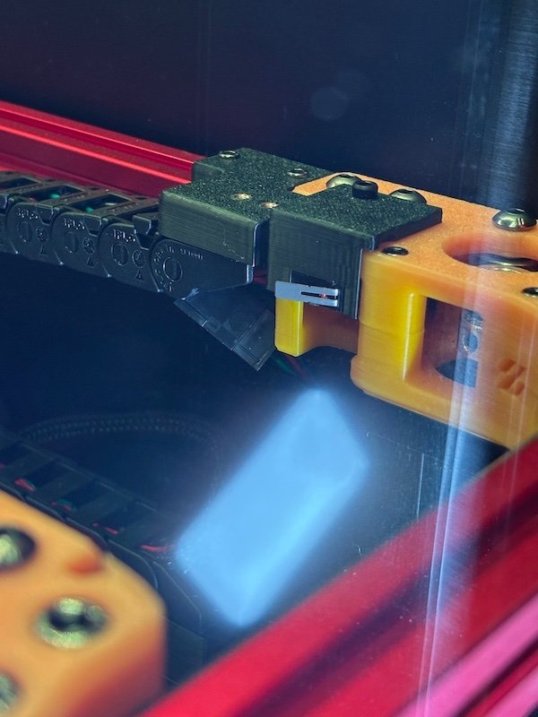
Pogo connector:
3 points


.jpg.25b6c23daab3edb3c5122f773f481e40.jpg)


.thumb.jpg.2c46f4b6100ff3eadfa9603cb6238e03.jpg)