Jump to content

12 Screenshots

  • Like 15
  • Voron FTW! 6
  • Thanks 2

Recommended Comments


On 2/19/2024 at 8:01 AM, RiddimnBrass said:

First method: standard mgn12 front mounted onto a standard 20x20 extrusion, about 4.5mm off the front face of the extrusion due to mounting hardware used. The belt sits in the bottom channel of the extrusion, about 1mm below the actual channel with the teeth facing up. This doesn't need to be precise, as long as the belt is centered within the channel it will work, there is plenty of slack for the belt to move down a bit in the z axis and doesnt have to be fully inside of the channel.

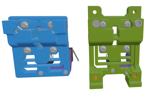
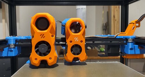
It has been a few months, but I have worked up a new x-frame set for the Ender 3 with a front facing MGN12H linear rail/carriage. This is derived from a Switchwire x-carriage and uses two M3x40 SHCS and nuts to connect the two halves together. There is a toothed wedge that fits in from below and clamps both belt ends in place. It requires four M3x10 BHCS to secure the assembled x-carriage to the MGN12H linear carriage. Two M3x45 BHCS secure the Mini Stealth core to the x-carriage but they require 1.5mm of shim washers on each screw to avoid hitting the MGN12H linear carriage when installing.

When installed, the nozzle sits 9.3mm lower than with a stock Ender 3 setup and 20.7mm further forward.

EDIT: The original x-frame left/right pieces extended slightly behind the 2020 gantry extrusion and would foul on the plates that hold the V-wheels for Z axis travel. The new pieces should have enough clearance. 

EDIT 2: This fits on an MGN12H linear carriage and not on the shorter MGN12C as stated before.

2024-06-16-141616_816x788_scrot.thumb.png.f8c40021047272c2560b4f86331ca4ee.png

2024-06-16-135702_865x723_scrot.png.08ee8ad25073e4478ffb209772687f0a.png

20240616_113158.thumb.jpg.079d6baa9e40789c5b059140008c6f8e.jpg

I am working on applying this design to a front mounted MGN9H linear carriage and then I will design x-carriages for MGN9H and MGN12H top mounted linear rail setups.

Belt Clamping Wedge.stl


Ender3_MGN12H_Front_x-frame_Left_v1.1.stl Ender3_MGN12H_Front_x-frame_Right_v1.1.stl

Edited by atrushing
  • Like 1
Link to comment
Share on other sites
On 2/19/2024 at 8:01 AM, RiddimnBrass said:

First method: standard mgn12 front mounted onto a standard 20x20 extrusion, about 4.5mm off the front face of the extrusion due to mounting hardware used. The belt sits in the bottom channel of the extrusion, about 1mm below the actual channel with the teeth facing up. This doesn't need to be precise, as long as the belt is centered within the channel it will work, there is plenty of slack for the belt to move down a bit in the z axis and doesn't have to be fully inside of the channel.

Here is the MGN9H front mounted Ender 3 x-carriage. Its requirements are almost identical to the MGN12H version in the above post. The MGN9 linear rail cannot be mounted directly to the front of 2020 aluminum profile as the MGN12 rail can be. The uploaded files assume that the back of the linear rail sits 4.5mm in front of the 2020 extrusion.

Due to different linear rail mod-kits and mounting brackets, I cannot make one universal-fit version of this file. There is an included 1mm thick spacer to fit between the MGN9H carriage and the back of the printed x-carriage if needed. This can be scaled in the Z axis within the slicer to the thickness needed for any given setup and may need to be test fit until the belt attachment lines up properly below the 2020 extrusion.

2024-06-16-233023_824x575_scrot.png.54e205b25bb4cd6d86d88a0028e874ef.png

Ender3_MGN9H_Front_x-frame_Left.stl Ender3_MGN9H_Front_x-frame_Right.stl Belt Clamping Wedge.stl 1mm_thick_MGN9H_Spacer.stl

Link to comment
Share on other sites
On 2/19/2024 at 8:01 AM, RiddimnBrass said:

Second method (my preferred method): standard mgn12 top mounted onto a 20x20 extrusion, about 4.5mm above the face of the extrusion due to mounting hardware used. Belt in same spot and same details apply. the mounting pattern would be the 2x m4(?) bolts that default ender 3 backplate uses (2 larger holes at top left and right of the backplate in the first paragraph). The stock bolts are long enough to make the mounting bracket about 3-3.25mm thick while still having decent bite. Any thicker would need more/different hardware.

Here is another remix of the Switchwire x-carriage to fit on an MGN12H carriage top-mounted on an Ender 3 gantry. It is designed for the bottom of the linear rail to be 4.5mm above the top of the 2020 aluminum extrusion. If this distance is smaller then the belt will be secured a little lower below the extrusion but if the linear rail is mounted higher then I might need to stretch out the x-carriage.

2024-06-18-110715_837x714_scrot.png.2da50a91cbe4b8e3d0cf53d1f6ef0e7e.png

It uses two M3x40 SHCS and nuts to connect the two halves together. There is a shorter toothed wedge that fits in from below and clamps both belt ends in place. It requires four M3x8 BHCS to secure the assembled x-carriage to the MGN12H linear carriage. Two M3x40 BHCS secure the Mini Stealth core to the x-carriage.

This x-carriage moves the hotend up about 9mm and forward about 8mm compared to a stock Ender 3.

Ender3_MGN12H_Top_x-frame_Left.stl Ender3_MGN12H_Top_x-frame_Right.stl Belt Clamping Wedge_Short.stl

Edited by atrushing
Link to comment
Share on other sites

Hi, is there a mount for bambu + micro sherpa + biqu microprobe ? i would like to print this as a crop version if possible !
Anyway, keep the good work man !

Edited by K1ngk
Link to comment
Share on other sites
18 minutes ago, K1ngk said:

Hi, is there a mount for bambu + micro sherpa + biqu microprobe ? i would like to print this as a crop version if possible !
Anyway, keep the good work man !

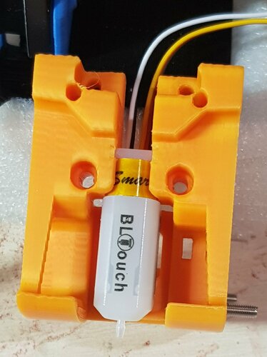
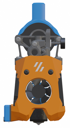
Which printer? This core with this cropped Diff IR shroud can fit the BL Touch on the side with this bracket. But on a Trident, V2.4 or Switchwire, you would use a standard cropped shroud with the appropriate MicroProbe x-carriage.

  • Like 1
Link to comment
Share on other sites
3 hours ago, K1ngk said:

Hi, i'm back to build it.

Problem : i have the CNC micro sherpa from mellow https://fr.aliexpress.com/item/1005005147276786.html?spm=a2g0o.order_list.order_list_main.10.73d55e5bsW1KgB&gatewayAdapt=glo2fra


but that's not aligned with the hole in the core for bambulab hotend.

Any solution ?

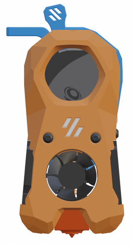
I have seen similar issues with Sherpa Minis that have been bought on Ali.. They modify the design slightly for easier/better manufacturing but that changes how it fits. Could you take a picture through the hole in the shroud (like below) so I can try to estimate how far the extruder is out of alignment? I could then make a core with the extruder mounting holes shifted so it can line up again. You might need to use flash to make sure the extruder is visible in the photo.

2024-08-10-172820_883x828_scrot.thumb.png.c49b91e23ad929f5045d992b8c850ea3.png

Or you could try to measure how far the mounting holes would need to be adjusted. It might take a couple test prints but I think we could get it to work.

Link to comment
Share on other sites

Thanks a lot, i think, it would need to move the screw around 3mm on the right, face to the part, for both of them


IMG_20240810_195646.jpg

Link to comment
Share on other sites
1 hour ago, K1ngk said:

Thanks a lot, i think, it would need to move the screw around 3mm on the right, face to the part, for both of them

I figured out why the extruder isn't lining up with the core.. I mirrored the Sherpa Micro so that I could put a filament release lever on the left side. The manufactured Micro is made in the standard orientation.

Here is a Bambu/Micro core with the mounting holes moved over by the 3mm but I think they will still need to move another 0.9mm. I will finish that and upload another core soon.

This also means that the shroud and the other pieces will need to be adjusted. I might need to make a complete set for a standard Sherpa Micro. The cable management pieces can be mirrored in the slicer but the shrouds will need more work.

MiniStealth_Core_Micro_Sherpa_CNC_Bambu.stl

Link to comment
Share on other sites

Lover over 3000 !

i'll try to print them in these days, i need to find a way to use the original part as i have nothing left ahah


thanks again for your amazing work !

  • Like 1
Link to comment
Share on other sites

Just to say thanks for your efforts and support.

I finally finished it for my v0.

I went for the cropped top in the end and bastardised the umbilical support. I am going to refit the original filament lever.

PXL_20240812_095417776.RAW-01.COVER.thumb.jpg.8d987030f76f59fb7d8a90bd45d61130.jpgPXL_20240812_095412920.RAW-01_MP.COVER.thumb.jpg.8ae833fc541024994e387bc95943fc6e.jpg

  • Like 2
Link to comment
Share on other sites
26 minutes ago, TitusADuxass said:

Just to say thanks for your efforts and support.

I finally finished it for my v0.

I went for the cropped top in the end and bastardised the umbilical support. I am going to refit the original filament lever.

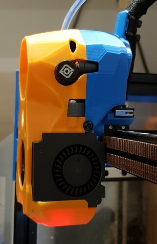
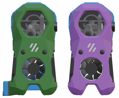
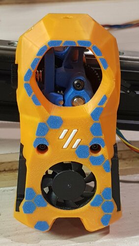
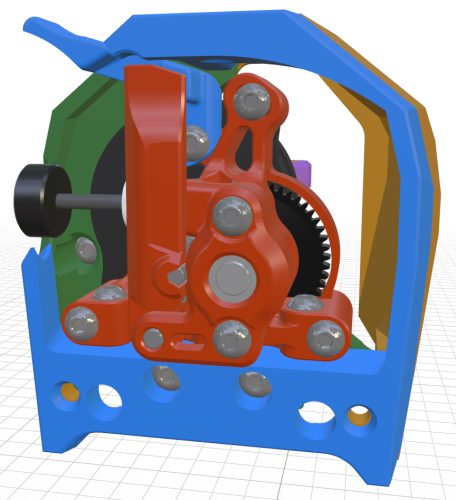
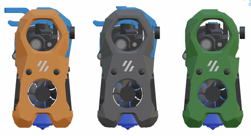
Looks nice with the carbon fiber front texture! The filament release lever isn't really necessary with the crop-top version and it makes sense to stick with the stock idler arm.

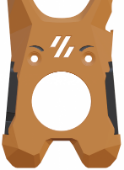
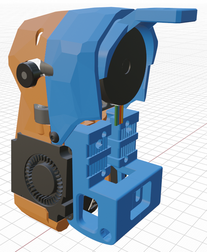
The intended orientation of the motor bridge (blue) tries to minimize how much of the stepper is covered so that the heat can radiate easier. I have seen a few people installing it the other way around though. Both sets of holes have the same 43.8mm spacing which makes it less clear which way to install it.

2024-08-12-122855_869x928_scrot.thumb.png.a79c94cedd54a7accbf02352048a4cab.png

Link to comment
Share on other sites
On 8/10/2024 at 8:03 PM, K1ngk said:

Thanks a lot, i think, it would need to move the screw around 3mm on the right, face to the part, for both of them


IMG_20240810_195646.jpg

Could you do me a favor and measure the depth of your CNC Sherpa Micro? I am wondering if they are using the shorter RIDGA gearset inside. My modified Micro is 24mm from front to back but it would be interesting if the Mellow version is similar.

2024-08-13-231922_512x754_scrot.thumb.png.783b1c29367024bd746c8ada7a3ba7d9.png

Link to comment
Share on other sites

@atrushing I just thought I'd make a short showing the mini stealth in operation.

I'm really pleased with it.

It works a lot better with 24v fans, the 5v fans didn't like 24v for some reason


  • Like 2
Link to comment
Share on other sites

(edit: added on github) x_carriage_frames_Beacon3D_MGN12.stl and bltouch for the Mini Sherpa both parts dont sit level on the bed also any way to hit eddy in the middle like the micro probe

Edited by chadak47
Link to comment
Share on other sites
9 hours ago, chadak47 said:

(edit: added on github) x_carriage_frames_Beacon3D_MGN12.stl and bltouch for the Mini Sherpa both parts dont sit level on the bed also any way to hit eddy in the middle like the micro probe

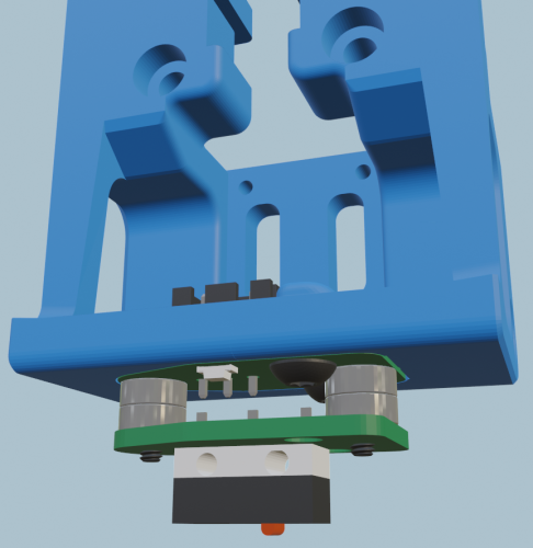
The BTT Eddy probe should fit in the standard Omron probe x-carriage with room to adjust the height from the build plate. Depending on your hotend, it might come a little close to the heat block.

2024-10-02-082326_660x823_scrot.thumb.png.a3237c42f25de09946ff3d55a6dd739a.png

Link to comment
Share on other sites
On 6/18/2024 at 8:44 AM, atrushing said:

Here is another remix of the Switchwire x-carriage to fit on an MGN12H carriage top-mounted on an Ender 3 gantry. It is designed for the bottom of the linear rail to be 4.5mm above the top of the 2020 aluminum extrusion. If this distance is smaller then the belt will be secured a little lower below the extrusion but if the linear rail is mounted higher then I might need to stretch out the x-carriage.

2024-06-18-110715_837x714_scrot.png.2da50a91cbe4b8e3d0cf53d1f6ef0e7e.png

It uses two M3x40 SHCS and nuts to connect the two halves together. There is a shorter toothed wedge that fits in from below and clamps both belt ends in place. It requires four M3x8 BHCS to secure the assembled x-carriage to the MGN12H linear carriage. Two M3x40 BHCS secure the Mini Stealth core to the x-carriage.

This x-carriage moves the hotend up about 9mm and forward about 8mm compared to a stock Ender 3.

Im finally getting around to finishing this, thanks a ton for putting in the effort. Does this version have provisions in any of the parts for a BL touch? I saw a few of them had a spot for it but Im not seeing a way with this set up. My exact setup needs sherpa mini, spider pro, bltouch, and top mounted 12h rail. I could also do it myself if I had the step file, looks like theres enough space for material to put it behind the hotend clamped between the two halves here.

Link to comment
Share on other sites
1 hour ago, RiddimnBrass said:

Im finally getting around to finishing this, thanks a ton for putting in the effort. Does this version have provisions in any of the parts for a BL touch? I saw a few of them had a spot for it but Im not seeing a way with this set up. My exact setup needs sherpa mini, spider pro, bltouch, and top mounted 12h rail. I could also do it myself if I had the step file, looks like theres enough space for material to put it behind the hotend clamped between the two halves here.

In order to fit the BL-Touch behind the hotend, we would need to move the toolhead forward by at least 6mm to clear the electric connector on the back and the hotend heat block in the front. If you were front-mounting the MGN12 rail, I would suggest the Biqu MicroProbe but it won't fit any better than the BL-Touch with a top-mounted rail.

2024-10-18-221459_1004x915_scrot.thumb.png.235672dd35b581e04563b5ea7057d63e.png

This is possible but there are also the left or right side mounted versions with brackets for a few different probes.

2024-09-16-235145_736x755_scrot.thumb.png.0e55735a9e9ab3457d68055601db3617.png

Sorry about the lack of a .step file but I just do raw mesh editing in Blender.

Link to comment
Share on other sites

Join the conversation

You can post now and register later. If you have an account, sign in now to post with your account.

Guest
Add a comment...

×   Pasted as rich text.   Paste as plain text instead

  Only 75 emoji are allowed.

×   Your link has been automatically embedded.   Display as a link instead

×   Your previous content has been restored.   Clear editor

×   You cannot paste images directly. Upload or insert images from URL.


User Feedback

×
×
  • Create New...