21 14 2 Details Changelog 0 Questions 638 Comments 3 Reviews 1 Tutorial Support Recommended Comments Prev 6 7 8 9 10 11 12 13 14 15 16 Next Page 11 of 26 Wick 124 Posted March 7, 2023 Share hmm this is heavy to print and I broke it when removing from plate as it has no stability as the middle part is very thin. So I tried to modify it with a Part of your standard Led-Carrier to get more stability and get rid of the included support (I just cut and merged it within the slicer as I'm not that far enough to do it with blender.....omg it's so much different to other Cad-software). it's just printing...... Mini_Stealth_BARF-Logo-Led_Carrier_Wick.stl Quote Link to comment Share on other sites More sharing options... atrushing 994 Posted March 7, 2023 Share 20 minutes ago, Wick said: I tried to modify it with a Part of your standard Led-Carrier to get more stability That is probably a good idea and a better print orientation. My mind has been too spread out lately with too many different designs.. 22 minutes ago, Wick said: blender.....omg it's so much different to other Cad-software True, it is like using MS Paint instead of Photoshop. But when you get used to the tools it can be very powerful. Quote Link to comment Share on other sites More sharing options... Wick 124 Posted March 7, 2023 Share ok, looks fine so far, many many thanks!! Now have to try with barf itself (have to remove from current running stealth). When trying I saw that there's no hole for fixing the led carrier in place (but its there in your .blend)? and that the Led-carrier could be longer by about 3mm to better fit in the lower guide Next thing I'd like to ask if it would be possible to get the Heat inswerts in from the lower side up to the extruder so they can't be pulled out, when I look through by not so well glassed Eyes it should be possible to get the inserts in from the Part fan side with a flat soldering tip (and maybe a small cutout of the Part fan wall on the left side at back view like in the pic above) Quote Link to comment Share on other sites More sharing options... atrushing 994 Posted March 7, 2023 Share 1 hour ago, Wick said: When trying I saw that there's no hole for fixing the led carrier in place (but its there in your .blend)? That hole was a very early feature that I have never used. Once the logo diffuser is in, the LED carrier becomes a press fit. I think I need to take a break from working on the Mini Stealth for a while as I have two disassembled printers that need some attention. Quote Link to comment Share on other sites More sharing options... Wasser Zeichen 13 Posted March 8, 2023 Share A new question has arisen. Due to the smaller dimensions of the Mini Stealth, the nozzle and bed of the V2 no longer fit together. It looks like the bed needs to be pushed back a bit. Left/Right cannot be changed. Am I correct in my assumption? I'm just wondering if resetting the bed still fits with the KlickyNG arm or if it collides when printing is at the very back? Quote Link to comment Share on other sites More sharing options... atrushing 994 Posted March 8, 2023 (edited) Share 48 minutes ago, Wasser Zeichen said: A new question has arisen. Due to the smaller dimensions of the Mini Stealth, the nozzle and bed of the V2 no longer fit together. It looks like the bed needs to be pushed back a bit. Left/Right cannot be changed. When I designed this to fit in my Trident I kept the nozzle as close to the stock position as possible. In this picture, the nozzle on the Mini Stealth sits 2mm higher than the Stealthburner but is at the same X and Y coordinates. I don't think the bed location needs to be adjusted. I did move the recess for the Omron probe back by 3.3mm to allow me to rotate the hotend away from the LEDs. I guess this will affect the docking for the Klicky probe. Here is a picture showing the official x-frame pieces in pink. Edited March 8, 2023 by atrushing Quote Link to comment Share on other sites More sharing options... Wasser Zeichen 13 Posted March 9, 2023 Share I found a new problem. I can't move the MiniSB all the way to the left on the X axis on a V2. The top inner screw head of the left X axis bracket collides with the bottom curve of the EBB board. Would it be possible to put the EBB holder screws 5mm higher on your Umbilincal holder? The EBB should slide up enough to have air down. Quote Link to comment Share on other sites More sharing options... atrushing 994 Posted March 9, 2023 Share 4 hours ago, Wasser Zeichen said: Would it be possible to put the EBB holder screws 5mm higher on your Umbilincal holder? The EBB should slide up enough to have air down. I am working on it but the geometry is messy so it will take a bit longer. I am actually moving the screws to the Orbiter down but it will have the same affect. Quote Link to comment Share on other sites More sharing options... Wasser Zeichen 13 Posted March 10, 2023 Share Thank you for taking care of the problem! I just put the EBB holes up in a hurry. Bore after bore, the previous ones closed. It works. There is now enough distance so that the EBB no longer touches the screw head. But that's more quick&dirty with MS 3DBuilder. Quote Link to comment Share on other sites More sharing options... Wasser Zeichen 13 Posted March 10, 2023 Share As a welcome side effect, the max. accelerations with the miniSB are much higher than with the standard one. Great work! 3 Quote Link to comment Share on other sites More sharing options... atrushing 994 Posted March 10, 2023 Share 10 minutes ago, Wasser Zeichen said: Thank you for taking care of the problem! I just put the EBB holes up in a hurry. Bore after bore, the previous ones closed. It works. There is now enough distance so that the EBB no longer touches the screw head. But that's more quick&dirty with MS 3DBuilder. I had never heard of that software.. It looks pretty useful. Nice work in solving the problem! I finished up my new version of the umbilical mount. I think it is worth keeping the old one for use in the V0.1/V0.2 but here is the raised version. The whole part will sit 5mm higher on the back of the stepper. Umbilical_Mount_Mini_SB_Orb2.0_raised.stl Quote Link to comment Share on other sites More sharing options... Wasser Zeichen 13 Posted March 10, 2023 Share Yes great! Thanks! I will change to ur new version at the next maintenance and will be the first test print Quote Link to comment Share on other sites More sharing options... Dracomagus79 0 Posted March 15, 2023 Share Does the orbiter filament sensor fits with these parts? I expect the shroud doesn't, but without it? Quote Link to comment Share on other sites More sharing options... atrushing 994 Posted March 15, 2023 Share 12 minutes ago, Dracomagus79 said: Does the orbiter filament sensor fits with these parts? I expect the shroud doesn't, but without it? If you do the crop-top it should fit just fine. You probably won't be able to use the filament_release_lever but the filament latch would be fully accessible. Quote Link to comment Share on other sites More sharing options... Wick 124 Posted March 15, 2023 Share Beacon probe arrived today and fits the x-carriage well. pcb is about 0,5mm lower than the part cooling outlets. measurements for mini-sb-rapido: base to cooling outlets : 51mm base to mounted beacon: 51,5mm head of mounting screws 1,8mm so total mounted beacon mesures 53,3mm Assuming the Rapido measures 54mm there should be a clearance of 2,5mm from the beacon measuring surface and total clearance of 0,7mm from the beacon screws to the printbed whith touching nozzle. Hope this is what it should be? 1 1 Quote Link to comment Share on other sites More sharing options... Wasser Zeichen 13 Posted March 15, 2023 Share 2 hours ago, Wick said: Beacon probe arrived today and fits the x-carriage well. pcb is about 0,5mm lower than the part cooling outlets. measurements for mini-sb-rapido: base to cooling outlets : 51mm base to mounted beacon: 51,5mm head of mounting screws 1,8mm so total mounted beacon mesures 53,3mm Assuming the Rapido measures 54mm there should be a clearance of 2,5mm from the beacon measuring surface and total clearance of 0,7mm from the beacon screws to the printbed whith touching nozzle. Hope this is what it should be? Oh great! That sounds good. But what I haven't read out now, does the beacon now fit without adjustment if a Rapido HF is installed? How exactly does the beacon work and is it sensitive to this heat? Can the Beacon also be connected to an EBB36? Do you know of a source for the beacon from Germany? Quote Link to comment Share on other sites More sharing options... atrushing 994 Posted March 15, 2023 Share 2 hours ago, Wick said: Sweet! 2 hours ago, Wick said: Assuming the Rapido measures 54mm there should be a clearance of 2,5mm from the beacon measuring surface and total clearance of 0,7mm from the beacon screws to the printbed whith touching nozzle. Hope this is what it should be? Your measurements match the 3D models I've found from the different suppliers. The Beacon probe .stl shows 2.6mm from the print surface so everything seems to line up close enough. On their website they show the probe secured with flat head screws. That could give you a little more clearance above the build plate. Quote Link to comment Share on other sites More sharing options... Wasser Zeichen 13 Posted March 15, 2023 Share Too bad Beacon is not recommended for embedded magnets in bed or even magnet surfaces for PEI adhesion. But thanks for the info! Quote Link to comment Share on other sites More sharing options... Wick 124 Posted March 15, 2023 Share if you could find some time and your Printers are ready could you pls implement zip-tie openings in the x-frame left on the back and side? this would enable a structured cabling from X-endstop Microswitch / Probes up to the EBB/Main wiring harness.... something like this: Quote Link to comment Share on other sites More sharing options... atrushing 994 Posted March 15, 2023 Share 5 minutes ago, Wick said: implement zip-tie openings in the x-frame left on the back and side? this would enable a structured cabling from X-endstop Microswitch / Probes up to the EBB/Main wiring harness.... something like this: That looks like a good idea and should be pretty easy to add. I'll start looking into where I could fit them. I had just figured that the wires could route to the inside to where the Omron capacitive probe normally fits (through the red sections) since the probe won't be there when using the Beacon. 1 Quote Link to comment Share on other sites More sharing options... Ducky4546 200 Posted March 17, 2023 Share It's amazing what more heat (260c) and %30 fan will do for this print. It came out great! I'm excited to get wiring. Printed on a Cr6 SE with Klipper 2 Quote Link to comment Share on other sites More sharing options... atrushing 994 Posted March 17, 2023 Share 11 minutes ago, Ducky4546 said: It came out great! I'm excited to get wiring. Printed on a Cr6 SE with Klipper Looks great! I'm looking forward to seeing your Replicator finished up. 1 Quote Link to comment Share on other sites More sharing options... atrushing 994 Posted March 17, 2023 Share On 3/15/2023 at 11:01 PM, Wick said: could you pls implement zip-tie openings in the x-frame left on the back and side? this would enable a structured cabling from X-endstop Microswitch / Probes up to the EBB/Main wiring harness.... something like this: Will this work? x_frame_Mini_Stealth_left_Beacon_zip-ties.stl 3 Quote Link to comment Share on other sites More sharing options... Wick 124 Posted March 18, 2023 Share wow, exactly as I imagined, looks great, will print and report, many thanks!! 1 Quote Link to comment Share on other sites More sharing options... Wick 124 Posted March 18, 2023 Share made a fast testprint of PETG in a bright colour for better view on the Prusa as the Voron is busy, tight fit for the 2,5 x 1mm zip-ties but goes through when pushing/pulling a little harder, positions are perfect from my point of view, I'm loving it!! would be absolutely great if you could find a way of pullthrough heatsets for mounting the orbiter like the mount of the Mini-SB to the x-carriage, i already pulled out the inserts a little and can't really fix it more than "handwarm" 2 Quote Link to comment Share on other sites More sharing options... Prev 6 7 8 9 10 11 12 13 14 15 16 Next Page 11 of 26 Join the conversation You can post now and register later. If you have an account, sign in now to post with your account. Add a comment... × Pasted as rich text. Paste as plain text instead Only 75 emoji are allowed. × Your link has been automatically embedded. Display as a link instead × Your previous content has been restored. Clear editor × You cannot paste images directly. Upload or insert images from URL. × Desktop Tablet Phone Submit Comment
Wick 124 Posted March 7, 2023 Share hmm this is heavy to print and I broke it when removing from plate as it has no stability as the middle part is very thin. So I tried to modify it with a Part of your standard Led-Carrier to get more stability and get rid of the included support (I just cut and merged it within the slicer as I'm not that far enough to do it with blender.....omg it's so much different to other Cad-software). it's just printing...... Mini_Stealth_BARF-Logo-Led_Carrier_Wick.stl Quote Link to comment Share on other sites More sharing options...
atrushing 994 Posted March 7, 2023 Share 20 minutes ago, Wick said: I tried to modify it with a Part of your standard Led-Carrier to get more stability That is probably a good idea and a better print orientation. My mind has been too spread out lately with too many different designs.. 22 minutes ago, Wick said: blender.....omg it's so much different to other Cad-software True, it is like using MS Paint instead of Photoshop. But when you get used to the tools it can be very powerful. Quote Link to comment Share on other sites More sharing options...
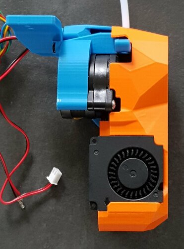
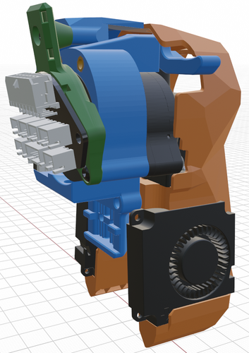
Wick 124 Posted March 7, 2023 Share ok, looks fine so far, many many thanks!! Now have to try with barf itself (have to remove from current running stealth). When trying I saw that there's no hole for fixing the led carrier in place (but its there in your .blend)? and that the Led-carrier could be longer by about 3mm to better fit in the lower guide Next thing I'd like to ask if it would be possible to get the Heat inswerts in from the lower side up to the extruder so they can't be pulled out, when I look through by not so well glassed Eyes it should be possible to get the inserts in from the Part fan side with a flat soldering tip (and maybe a small cutout of the Part fan wall on the left side at back view like in the pic above) Quote Link to comment Share on other sites More sharing options...
atrushing 994 Posted March 7, 2023 Share 1 hour ago, Wick said: When trying I saw that there's no hole for fixing the led carrier in place (but its there in your .blend)? That hole was a very early feature that I have never used. Once the logo diffuser is in, the LED carrier becomes a press fit. I think I need to take a break from working on the Mini Stealth for a while as I have two disassembled printers that need some attention. Quote Link to comment Share on other sites More sharing options...
Wasser Zeichen 13 Posted March 8, 2023 Share A new question has arisen. Due to the smaller dimensions of the Mini Stealth, the nozzle and bed of the V2 no longer fit together. It looks like the bed needs to be pushed back a bit. Left/Right cannot be changed. Am I correct in my assumption? I'm just wondering if resetting the bed still fits with the KlickyNG arm or if it collides when printing is at the very back? Quote Link to comment Share on other sites More sharing options...
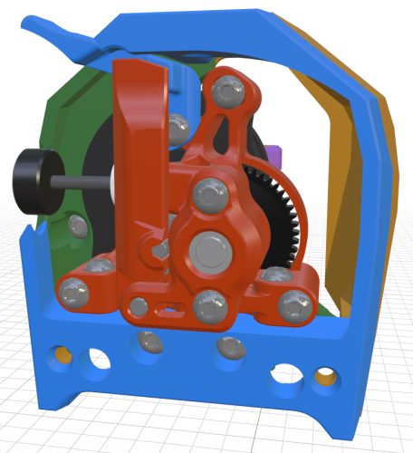
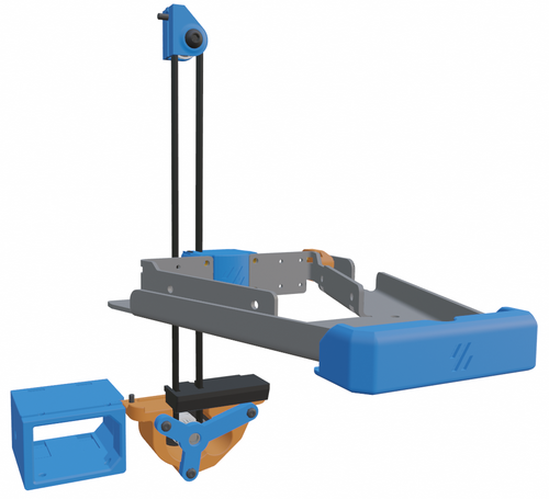
atrushing 994 Posted March 8, 2023 (edited) Share 48 minutes ago, Wasser Zeichen said: A new question has arisen. Due to the smaller dimensions of the Mini Stealth, the nozzle and bed of the V2 no longer fit together. It looks like the bed needs to be pushed back a bit. Left/Right cannot be changed. When I designed this to fit in my Trident I kept the nozzle as close to the stock position as possible. In this picture, the nozzle on the Mini Stealth sits 2mm higher than the Stealthburner but is at the same X and Y coordinates. I don't think the bed location needs to be adjusted. I did move the recess for the Omron probe back by 3.3mm to allow me to rotate the hotend away from the LEDs. I guess this will affect the docking for the Klicky probe. Here is a picture showing the official x-frame pieces in pink. Edited March 8, 2023 by atrushing Quote Link to comment Share on other sites More sharing options...
Wasser Zeichen 13 Posted March 9, 2023 Share I found a new problem. I can't move the MiniSB all the way to the left on the X axis on a V2. The top inner screw head of the left X axis bracket collides with the bottom curve of the EBB board. Would it be possible to put the EBB holder screws 5mm higher on your Umbilincal holder? The EBB should slide up enough to have air down. Quote Link to comment Share on other sites More sharing options...
atrushing 994 Posted March 9, 2023 Share 4 hours ago, Wasser Zeichen said: Would it be possible to put the EBB holder screws 5mm higher on your Umbilincal holder? The EBB should slide up enough to have air down. I am working on it but the geometry is messy so it will take a bit longer. I am actually moving the screws to the Orbiter down but it will have the same affect. Quote Link to comment Share on other sites More sharing options...
Wasser Zeichen 13 Posted March 10, 2023 Share Thank you for taking care of the problem! I just put the EBB holes up in a hurry. Bore after bore, the previous ones closed. It works. There is now enough distance so that the EBB no longer touches the screw head. But that's more quick&dirty with MS 3DBuilder. Quote Link to comment Share on other sites More sharing options...
Wasser Zeichen 13 Posted March 10, 2023 Share As a welcome side effect, the max. accelerations with the miniSB are much higher than with the standard one. Great work! 3 Quote Link to comment Share on other sites More sharing options...
atrushing 994 Posted March 10, 2023 Share 10 minutes ago, Wasser Zeichen said: Thank you for taking care of the problem! I just put the EBB holes up in a hurry. Bore after bore, the previous ones closed. It works. There is now enough distance so that the EBB no longer touches the screw head. But that's more quick&dirty with MS 3DBuilder. I had never heard of that software.. It looks pretty useful. Nice work in solving the problem! I finished up my new version of the umbilical mount. I think it is worth keeping the old one for use in the V0.1/V0.2 but here is the raised version. The whole part will sit 5mm higher on the back of the stepper. Umbilical_Mount_Mini_SB_Orb2.0_raised.stl Quote Link to comment Share on other sites More sharing options...
Wasser Zeichen 13 Posted March 10, 2023 Share Yes great! Thanks! I will change to ur new version at the next maintenance and will be the first test print Quote Link to comment Share on other sites More sharing options...
Dracomagus79 0 Posted March 15, 2023 Share Does the orbiter filament sensor fits with these parts? I expect the shroud doesn't, but without it? Quote Link to comment Share on other sites More sharing options...
atrushing 994 Posted March 15, 2023 Share 12 minutes ago, Dracomagus79 said: Does the orbiter filament sensor fits with these parts? I expect the shroud doesn't, but without it? If you do the crop-top it should fit just fine. You probably won't be able to use the filament_release_lever but the filament latch would be fully accessible. Quote Link to comment Share on other sites More sharing options...
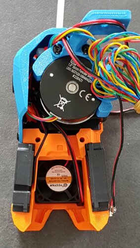
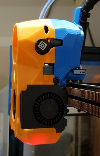
Wick 124 Posted March 15, 2023 Share Beacon probe arrived today and fits the x-carriage well. pcb is about 0,5mm lower than the part cooling outlets. measurements for mini-sb-rapido: base to cooling outlets : 51mm base to mounted beacon: 51,5mm head of mounting screws 1,8mm so total mounted beacon mesures 53,3mm Assuming the Rapido measures 54mm there should be a clearance of 2,5mm from the beacon measuring surface and total clearance of 0,7mm from the beacon screws to the printbed whith touching nozzle. Hope this is what it should be? 1 1 Quote Link to comment Share on other sites More sharing options...
Wasser Zeichen 13 Posted March 15, 2023 Share 2 hours ago, Wick said: Beacon probe arrived today and fits the x-carriage well. pcb is about 0,5mm lower than the part cooling outlets. measurements for mini-sb-rapido: base to cooling outlets : 51mm base to mounted beacon: 51,5mm head of mounting screws 1,8mm so total mounted beacon mesures 53,3mm Assuming the Rapido measures 54mm there should be a clearance of 2,5mm from the beacon measuring surface and total clearance of 0,7mm from the beacon screws to the printbed whith touching nozzle. Hope this is what it should be? Oh great! That sounds good. But what I haven't read out now, does the beacon now fit without adjustment if a Rapido HF is installed? How exactly does the beacon work and is it sensitive to this heat? Can the Beacon also be connected to an EBB36? Do you know of a source for the beacon from Germany? Quote Link to comment Share on other sites More sharing options...
atrushing 994 Posted March 15, 2023 Share 2 hours ago, Wick said: Sweet! 2 hours ago, Wick said: Assuming the Rapido measures 54mm there should be a clearance of 2,5mm from the beacon measuring surface and total clearance of 0,7mm from the beacon screws to the printbed whith touching nozzle. Hope this is what it should be? Your measurements match the 3D models I've found from the different suppliers. The Beacon probe .stl shows 2.6mm from the print surface so everything seems to line up close enough. On their website they show the probe secured with flat head screws. That could give you a little more clearance above the build plate. Quote Link to comment Share on other sites More sharing options...
Wasser Zeichen 13 Posted March 15, 2023 Share Too bad Beacon is not recommended for embedded magnets in bed or even magnet surfaces for PEI adhesion. But thanks for the info! Quote Link to comment Share on other sites More sharing options...
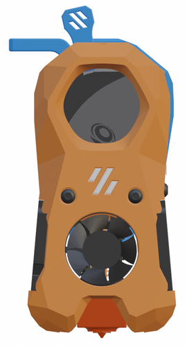
Wick 124 Posted March 15, 2023 Share if you could find some time and your Printers are ready could you pls implement zip-tie openings in the x-frame left on the back and side? this would enable a structured cabling from X-endstop Microswitch / Probes up to the EBB/Main wiring harness.... something like this: Quote Link to comment Share on other sites More sharing options...
atrushing 994 Posted March 15, 2023 Share 5 minutes ago, Wick said: implement zip-tie openings in the x-frame left on the back and side? this would enable a structured cabling from X-endstop Microswitch / Probes up to the EBB/Main wiring harness.... something like this: That looks like a good idea and should be pretty easy to add. I'll start looking into where I could fit them. I had just figured that the wires could route to the inside to where the Omron capacitive probe normally fits (through the red sections) since the probe won't be there when using the Beacon. 1 Quote Link to comment Share on other sites More sharing options...
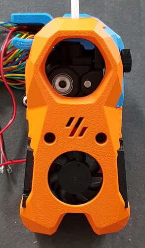
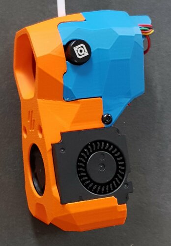
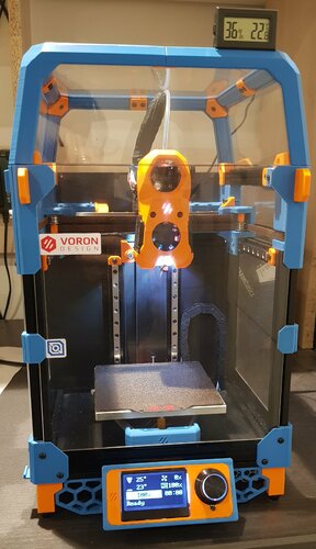
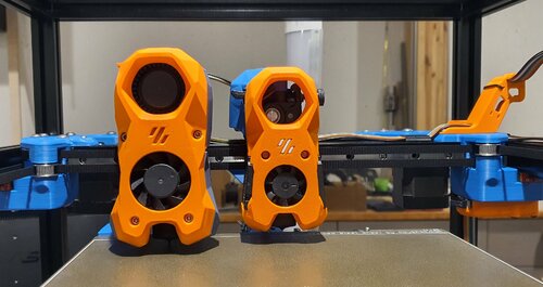
Ducky4546 200 Posted March 17, 2023 Share It's amazing what more heat (260c) and %30 fan will do for this print. It came out great! I'm excited to get wiring. Printed on a Cr6 SE with Klipper 2 Quote Link to comment Share on other sites More sharing options...
atrushing 994 Posted March 17, 2023 Share 11 minutes ago, Ducky4546 said: It came out great! I'm excited to get wiring. Printed on a Cr6 SE with Klipper Looks great! I'm looking forward to seeing your Replicator finished up. 1 Quote Link to comment Share on other sites More sharing options...
atrushing 994 Posted March 17, 2023 Share On 3/15/2023 at 11:01 PM, Wick said: could you pls implement zip-tie openings in the x-frame left on the back and side? this would enable a structured cabling from X-endstop Microswitch / Probes up to the EBB/Main wiring harness.... something like this: Will this work? x_frame_Mini_Stealth_left_Beacon_zip-ties.stl 3 Quote Link to comment Share on other sites More sharing options...
Wick 124 Posted March 18, 2023 Share wow, exactly as I imagined, looks great, will print and report, many thanks!! 1 Quote Link to comment Share on other sites More sharing options...
Wick 124 Posted March 18, 2023 Share made a fast testprint of PETG in a bright colour for better view on the Prusa as the Voron is busy, tight fit for the 2,5 x 1mm zip-ties but goes through when pushing/pulling a little harder, positions are perfect from my point of view, I'm loving it!! would be absolutely great if you could find a way of pullthrough heatsets for mounting the orbiter like the mount of the Mini-SB to the x-carriage, i already pulled out the inserts a little and can't really fix it more than "handwarm" 2 Quote Link to comment Share on other sites More sharing options...


 21
21
 14
14
 2
2
Recommended Comments
Join the conversation
You can post now and register later. If you have an account, sign in now to post with your account.