


-
 21
21
-
 14
14
-
 2
2

User Feedback
-
Similar Content
-
- 0 comments
- 996 views
-
- 20 comments
- 15,820 views
-
- 4 comments
- 17,363 views
-
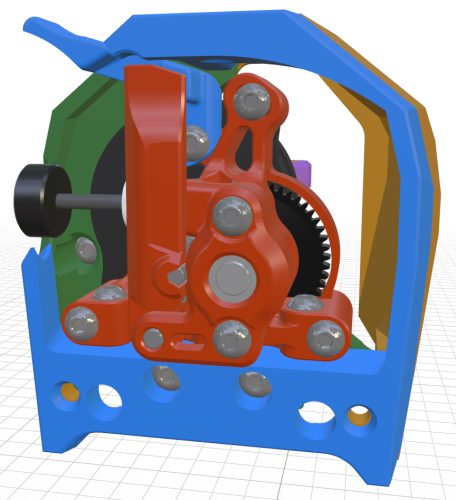
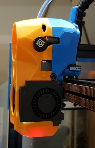
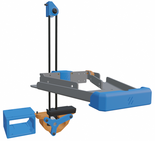
Bowden tube guide + CANBUS Wire support PTFE Arm
By GalvanicGlaze,
- canbus
- galvanicglaze
- (and 3 more)
- 1 comment
- 12,601 views
-
- 6 replies
- 1,442 views
-
-


Recommended Comments
Join the conversation
You can post now and register later. If you have an account, sign in now to post with your account.