-
TeamFDM.com is an UNOFFICIAL companion site for the DIY Voron 3D printer community. For official docs and final source of truth, visit the Official Voron Discord or the Voron Github
Printable Voron User Mods
Voron User Mods, or "UserMods", are a collection of community created and Team FDM curated modification for Voron Printers. All of these mods are available on the VoronUsers Github repo and unless otherwise specified follow the Voron communities GPL3.0 Licensing. Use any Mods at your own risk, if you make modification please share them on the VoronUsers repo.
Mod Authors: Have a Voron mod? Upload it at TeamFDM.com and let us know you're the author. We will ensure you can update and curate your files for more feedback! Please include tags for what Voron, or extruder your mod is compatible with.
652 files
-

1515 Led Mount
Snap in 1515 LED mount for WS2812B led strips.
BOM:
WS2812BECO Black PCB - 5m 60 IP30 Some cables A soldering iron and some solder JST-XH Crimps Notes about the WS2812: 30 leds per meter fits, but you will only have a led in every second diffuser. 60leds per meter is the perfect fit. Print guide:
Print 9 left and 9 right.
Preparation:
I use 9 led's on each side. Solder the cables. Now it's a good idea to test and configure the neopixels too, so you don't have to take it out again after you've mounted it, in case something is wrong. Just hang them over the spool holder and make sure nothing can short circuit while testing.
Mounting:
Guide the cables through the 1515 extrusion over the mid-panel. Push one diffuser in. (Do this in the front with the led strip as far back as possible) Slide the diffuser back while guiding the led strip through it. One by one. When you get to the last diffuser on either side, you have to partially insert the strip into the diffuser. Then carefully try to bend/align it with the 1515 slot and carefully pop it into place. Having it all the way to the front gives you more leeway to bend without damaging the strip. Do the same on the other side. After you can wire them in parallel and connect them to the BTT SKR Mini E3 V2 neopixel slot. Klipper config for BTT SKR Mini E3 V2:
[neopixel case_lights] ## Chamber Lighting - In 5V-RGB Position pin: PA8 chain_count: 9 initial_RED: 1 initial_GREEN: 1 initial_BLUE: 1 If this looks familiar contact me so i can credit you. This is based on some other 1515 mount. I just remade the rest. Heavily based on eddie's misumi holders.
82 downloads
(0 reviews)0 comments
Submitted
-
V0.1 Z Cover
Z Cover for v0.1
A cover to stop things from dropping down the Z motor and disappearing forever.
BOM:
2x M3x6 FHCS (Creative users might get away with sandwitching the deck panel inbetween using M3x8 SHCS/BHCS from the bottom) Print guide:
Print the 3 measuring tools to figure out what spacing suits your printer. Then print the
366 downloads
(1 review)0 comments
Submitted
-
Zodiac BMO Stealthburner Toolhead
Zodiac BMO Stealthburner Toolhead
A modified toolhead for use with the Zodiac BMO Hotend and compatible with RC1 of Stealthburner. It was created from the original RC1 Stealthburner Phaetus BMO Toolhead files. If changes after RC1 of Stealthburner make this mod incompatible, I will provide updated files based on the official Stealthburner CAD files. The official Zodiac3D CAD Model of their BMO Hotend was used for reference.
Images
Notes
For optimal fit it is very important that your printer's dimensional accuracy is nearly perfect. Especially Pressure Advance has to be tuned right. Even then it is still a very tight fit, when putting in the hotend. That ensures that it cannot twist or wiggle. One handed nozzle changes should be possible, but are generally not recommended.
The bowden tube length from top of the toolhead to the heatbreak of the hotend is around 31.2mm. Take that into account when calculating the total bowden length. (E.g. Clockwork2 needs 11mm above the toolhead, so that accumulates to a total bowden length of 42.2mm, when using Clockwork2.)
Test prints were made with standard ABS, ABS and ASA Carbon.
34 downloads
(0 reviews)0 comments
Submitted
-
SW SB CRTouch
Voron Switchwire StealthBurner CR Touch Mod
This repo contains the STL for Voron SW SB CR Touch Mod.
I used the SB 1.05Beta during development. But it should work on the SB v1 release as it's only X rail carriage.
The STL is only for MGN12 Carriage for SW No supports are needed during the print No tools are needed to fit the CR Touch, it's a press fit I used Dragon Standard hotend for deciding height of CR touch and it's 2mm above the nozzle when pin is up It should work with other hotends as well (Hotends of same form factor as Dragon) Preview of how CR Touch Fits in the SB X rail carriage:
Thanks to Voron Developers for building rocket making tools
127 downloads
-
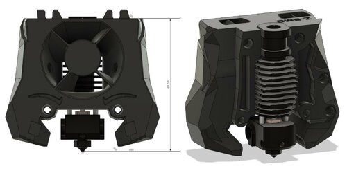
Crazy Mozzie Cw2
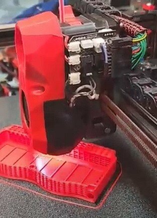
Stealthburner Clockwork2 Toolhead for HF Crazy Mozzie
This is a a toolhead mount for the HF Crazy Mozzie (or other Mosquito clones), compatible with Stealthburner RC1 and Clockwork 2. Design source.
The airflow pattern is designed and tested for the high-flow version. Here it is shown with the regular version:
In action:
166 downloads
(0 reviews)0 comments
Submitted
-
EBB36 mount for Orbiter extruder
EBB36 mount for Orbiter extruder
Amended version of:
107 downloads
- stealthburner
- trident
- (and 2 more)
(0 reviews)0 comments
Submitted
-
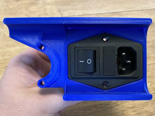
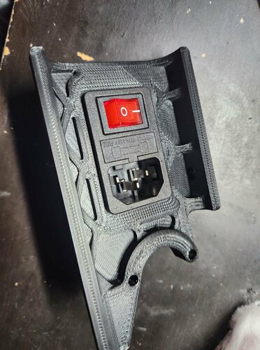
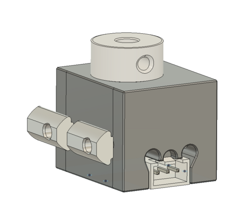
Power Inlet for FN 283/FN 284 Switch-Filter with LR Wings
This is my first functional 3d printer part remix, I used https://www.teamfdm.com/files/file/205-powerskirt-fn284-10-06/ and inset it into the power inlet part.
48 downloads
(0 reviews)0 comments
Submitted
-
Alternative MagProbe for heat-resistant SSG Micro-Switch
One of my goal was to print Polycarbonate (PC) as smoothly as possible.
Unfortunately, PC is notorious for heavy warping. A possible countermeasure is to raise the chamber temp - in my case to around 60°C.
(Be sure, that every component within your chamber can take the heat.)
Around that temperature I found that the magnetic probe and the regular Micro-Switch probe aren't reliable anymore.
So, I switched to a SSG-5P Micro-Switch, which is heat-resistant up to 120°C.
The magnetic probe is a bit wider than the regular probe. Therefore, you have to reprint the X-Carriage. As of now, I redesigned the X-Carriage for CW1 - not CW2.
Original probe made by Annex: https://github.com/Annex-Engineering/Quickdraw_Probe
60 downloads
(0 reviews)0 comments
Updated
-
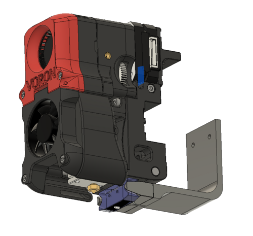
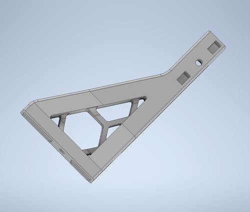
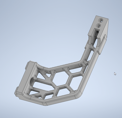
Trident Simple Internal Spool Holder + Bowden Guide 60degrees curved
My first Voron becomes ready part by part, by the mods i already have done it nearly wouldn't had been neccessary to buy the printed parts, but anyway...
I'm a fan of the Horseshoe Spool Holder from Logan Fraser, but it has the disadvantage that it only fits Spools with 20cm rims!
So I decided to create an extrusion mounted simple Universal Holder to the back using the standard extrusion frame holder that came with the printed parts. It can be used standalone or as in my case in addition to logans horseshoe. As both the horseshoe and the simple are extrusion mounted I can easy remove the bottom plate as I also use Logans Inverted Electronics (as well as his Pi Plate I also modified). To be able to have the Filament inserted from Horseshoe or my universal version I also made a curved Bowden Guide angled at 60 degrees to the extrusion. The curved outlet up to the toolhead is angled to guide the bowden to the extrusion to prevent the bowden touching the cabling of the stepper motor. The Bowden Guide needs a support (see pic below)
Parts needed:
SIS:
M5 x 20mm, M5-Nut (pull the nut into the holder with the M5x20 first), M5 x 10mm, M5 extrusion nut
Bowden Guide:
M3 x 8, M3 Hammerhead
Many thanks Logan for your incredible Mods!
As always, have fun
685 downloads
-
Mount for BIGTREETECH HDMI5 screen Trident / Voron 2.xxx
Thanks to sttts for his Bracket which allowed me to do this mount !!
https://github.com/VoronDesign/VoronUsers/tree/master/printer_mods/sttts/Waveshare-5.5-inch-HDMI-AMOLED
Disclaimer
may you needs to raise the Feets couple of mm , in my situation on trident i have to use 6mm raiser with longer M5 screws , maybe on the V2.4 not needed but i uploaded the raiser just in case .
Bom
Screen housing | 3x m3x6mm -- 3x M3 heast set inserts (voron BOM inserts ) Bracket | 3x m3x8mm -- 3x m3 2020 T-Nut .
BIGTREETECH HDMI5
i use Flexible Angled 90° HDMI / USB-C
angled Hdmi cable 1 angled USB-C
i Hope this help - and happy 3d printing
2,111 downloads
-
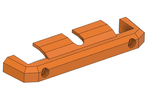
Trident-Decontaminator_Mount_right.stl
I've created a Trident mounting bracket for Decontaminator... As it's designed to be mounted on the right side of the extrusion the Purge bucket needs to be mirrored so the small bucket shows to the Z-axis end stop.
Pls. add 2 small supports for the 2 guides on the extrusion side.
It needs 1 pc. M5 x 10 + Extrusion Nut and 2 pc. M3 Heat-Inserts
Have fun, Wick!
204 downloads
(0 reviews)0 comments
Updated
-
V0.1 Raised Tophat - Bottom Up Mod
This mod started out as a remix of the TophatHingeV0.1 mod by Demosth. To gain extra space for the extruder, bowden tube and cables I modified the four upper corner A/B Frame/Idler pieces. This raises the upper 1515 alu-profile pieces by 20mm so installing the standard tophat (or a hinged tophat) is functionally the same as with a stock V0.1. The most notable visual difference from a stock V0.1 is the extra space above the gantry.
I made up the extra height by adding 20mm tall strips of 3mm thick plexiglass at the bottom of the front and side panels. This mod would be easy to stretch and gain 10 or 20mm more if needed.
I 'borrowed' the extra plexiglass from my back panel pieces. In the LDO kit, they ship two separate pieces of dark glass for the back panel. The smaller one is meant to close off the print chamber and the larger one is meant to cover the lower electronics bay. With this mod the smaller piece is no longer large enough so it is necessary to use the larger one at the top.
I have included .stl files to install this with the stock tophat, as well as modified .stl files from Demosth's mod.
For the hinged version of this mod, I have also included my latching solution for the front of the tophat. The left and right Tophat_Front_Clips allow one to slide a thumb screw in to secure the top in place. The tophat_nut_catch just provides somewhere to stow the thumbscrew when the top is open (as shown in the pictures). I used the no-drop nut mod to make the square nut easier to manage.
NOTE: The original A/B Drive_Frame_Upper files that I uploaded had the back heat set insert hole in the wrong location. I have uploaded the correct version of these .slt files. (21 OCT 2022)
701 downloads
(0 reviews)0 comments
Updated
-
CW1 to Stealthburner PCB Mount.stl
While building my V2.4127 350mm Printer I wanted to use the SB PCB but I could not find a mount to attach it to the CW-1 extruder. Hence the remix of the two mounts so that you can transition from a SB with CW-1 using the SB PCB to the full SB with CW-2 tool head. you will need to us a 3mm heat insert in the middle mounting hole which is counter sunk in the back of the mount.
80 downloads
- stealthburner
- sb
- (and 2 more)
(0 reviews)0 comments
Updated
-
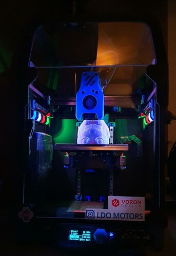
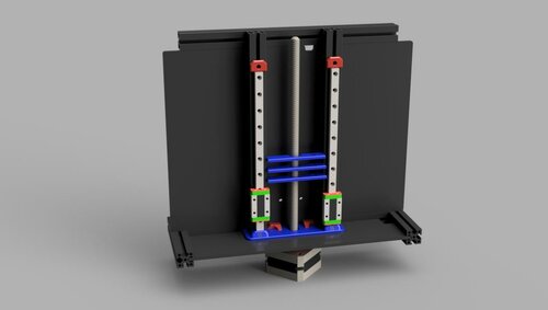
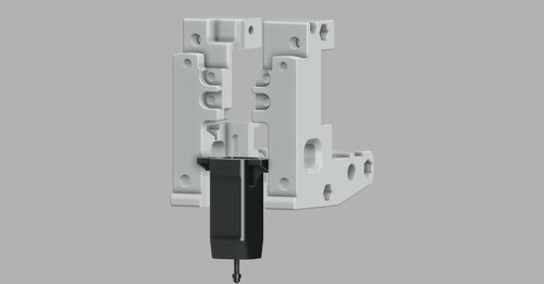
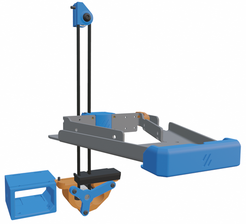
V0.1 Belted Z Mod - LDO Pancake Stepper - Kiragami Bed
This belted-z mod is designed to be as small as possible. It uses the LDO-36STH17 geared pancake stepper from the extruder that comes with the LDO V0.1 kit. This allows it to fit completely below the printer and not take any space from the electronics area on the back of the printer.
The 5:1 gearing of the 20t GT-2 pulley maintains the same 8mm rotation_distance as the stock z-leadscrew. I was able to increase my z-homing speed to 50mm/sec while lowering the current to 0.25A for the Z motor. The build plate will usually drop when the stepper enable is turned off.
B.O.M.
1 - LDO-36STH17 or OMC 14HR07-1004VRN 10 tooth geared pancake stepper
1 - 50T geared 5mm shaft (from Mini Afterburner extruder kit) (alternate source)
1 - 20T GT-2 pulley (5mm bore)
2 - MR85 bearing
2 - F695 flanged bearing
1 - M5 x 1mm shim spacer
3 - M3x8 BHCS
3 - M3 square nuts
2 - M3x12 BHCS
2 - M3x35 BHCS
1 - M5x16 BHCS
5 - printed parts (required)
1 - printed part (optional)
6 - M3 threaded heat inserts
When installing this mod I only had to pull out the bottom panel to access the screws holding the Z motor with lead screw. Installation of the new components was all done from the bottom and front of the printer.
I have included a Blender file to show the overall assembly of this mod.
630 downloads
-
v2.4 Voron 2.4 r2 Power Inlet IECGS 1.5mm
Since there was no file included in the official STLs for a 1.5mm IECGS power inlet, I created one using the same tolerances the official models (1mm, 1.2mm) use. Fits perfectly.
91 downloads
(0 reviews)0 comments
Updated
-
Alternative Z Endstop for heat-resistant SSG Micro-Switch
One of my goal was to print Polycarbonate (PC) as smoothly as possible.
Unfortunately, PC is notorious for heavy warping. A possible countermeasure is to raise the chamber temp - in my case to around 60°C.
(Be sure, that every component within your chamber can take the heat.)
Around that temperature I found that the magnetic probe and the regular Micro-Switch probe aren't reliable anymore.
So, I switched to a SSG-5P Micro-Switch, which is heat-resistant up to 120°C.
BOM:
SSG-5P GT2 20T 6mm JST 3Pin29 downloads
-
Voron 2.4 and Trident infinity enclosure by Clearview Plastics
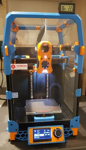
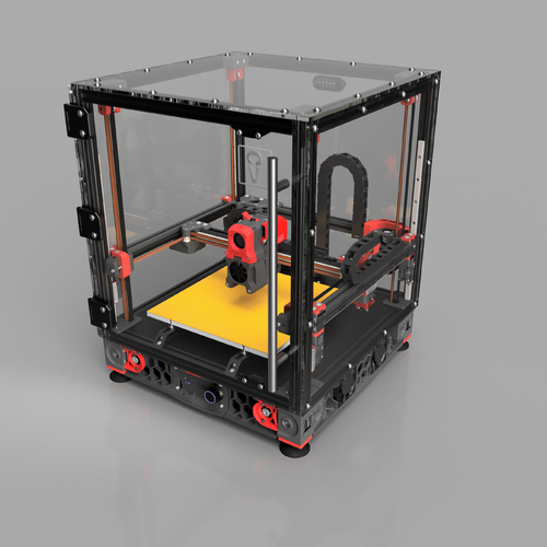
The Clearview Infinity mod for the Voron 2.4r2 and Trident is an upgraded enclosure system that offers both better performance with a commercial grade design aesthetic. The name "Clearview Infinity" correlates to the visual aesthetic of the transparent panels. 1/4" HD polycarbonate panels and oversized hardware are designed to take give this a commercial grade fit and finish. More so, the added function that this enclosure set adds is better heat retention for advanced printing, reduced noise while printing, and a strong sturdy enclosure that feels like a professional piece of lab equipment. All due respect to the Voron team for making an amazing printer, but we thought the enclosure portion needed some help.
Open Source mode:
We want to offer a way to open source this mod for those who DIY. At the same time, we build these enclosures to make a living and we put a lot of work into the design, function, and finish of the enclosures we make. That said, we will give you alternative open source parts that you can use to complete your own Clearview Infinity enclosure or it is available for purchase through our website. In the spirit of being a maker, we'll happy to share our idea and the work it takes to make a great product. 🙂
What is included (BOM)
5 Polycarbonate panels (5.5mm or 6mm) (Front, sides, rear, and top) 52 m5 x10mm flanged screws 52 m5 half round extrusion nuts 16 m4 x10mm flanged screws 12 m4 Rivet nuts 4 5mm x 10mmx 5mm magnets 1 - 256mm pull handle 1 press fit bowden holder 1/4" wide weather seal Printed parts
3 - 270 degree hinges 2 - Magnetic brackets 1 - combination rubber grommet
Panel 1 Front 421mm wide x 435.5mm tall Panel 2 + 3 Sides 410mm wide x 430mm tall Panel 4 Rear 421mm wide x 430mm tall Panel 5 Top 421mm wide x 415.5 deep Hinges 1/4" x 1/8 Gasket Material Interactive model
https://myhub.autodesk360.com/ue2bc5d44/g/shares/SH9285eQTcf875d3c53959473f32555af79b
60 downloads
-
-
Volcano-Mosquito - Mellow stealthBurner
Volcano-Mosquito - Mellow Pint-Head for stealthBurner
Hope this Help
367 downloads
(0 reviews)0 comments
Submitted
-
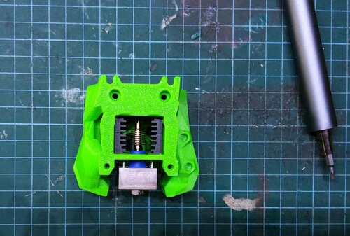
V0.1 Lower bay guard
I created this as a way to prevent filament from getting into the electronics bay via the space around the z-rod. This screws in place of the two z liner rail stops so you can use the existing nuts to mount it. per design, it is a snug fit, but allows for clearance around the z-rod so as not to hinder its movement. The face of this should be printed down and I only allowed supports for the holes. Please let me know what you think about this or if you'd like to see any changes.
178 downloads
-
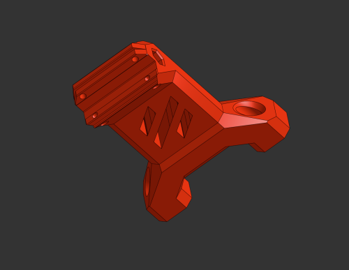
SSD Bracket
ssd_bracket
bracket to mount a ssd-drive to the din rail under a voron printer
This bracket is designed to mount a ssd drive in the electronic bay of a voron 2.4 or Trident.
The following part has to be printed x1: pcb_din_clip_x3
Bom:
1x ssd_bracket 1x pcb_din_clip 2x M2x10 self tapping screw 4x M3x12 SHCS Instructions:
Use the M2x10 self tapping screws to mount the ssd_bracket to the pcb_din_clip. Then mount your ssd drive with the M3x12 SHCS to the ssd_bracket. Then snap the assembly in place on the din rail. It mounts similar to the Raspberry Pi on page 178 to 179 on the Voron 2.4r2 manual.
70 downloads
-
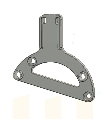
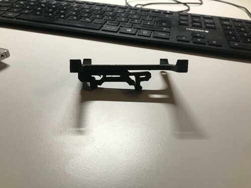
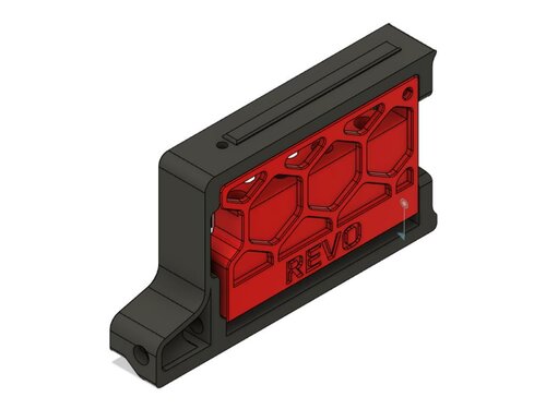
Revo Skirt Nozzle Holder
Revo Nozzle Holder v2.4 350mm
Remix of Andre's skirt-mounted nozzle holder to fit Voron 2.4 350mm printers, the BOM and installation steps are the same.
This will fit up to 4 nozzles, and uses the '300mm' part from Andre's design, unmodified (even though this uses the 300mm part from the Trident, it will only fit the 350mm v2 due to differences in skirt design).
Bill Of Materials
2x 6mm x 3mm Round Magnet 2x M3 Heat-set insert 2x M3x8 BHCS (SHCS will work as well) Instructions
Print skirt and nozzle holder parts (the skirt piece will be placed in the right-front position of the printer). Install the 2 heat-set inserts into the ends of nozzle-holder part. Install 1 magnet in the skirt, and 1 in the nozzle-holder such that they attract each other when the door is installed. Insert the nozzle holder into the skirt and fasten with 2 M3x8 BHCS Remove the stock skirt piece from your v2.4 and install the new one in its place (Note, you will likely need an angled hex driver or ball-end driver to install the skirt bolt with the nozzle tray installed).314 downloads
(0 reviews)0 comments
Submitted
-
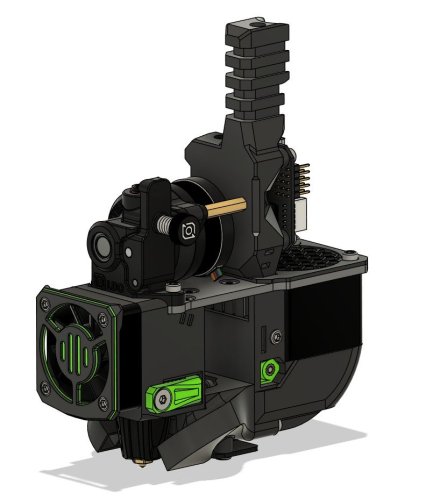
Stealthburner Crazy Dragon Toolhead
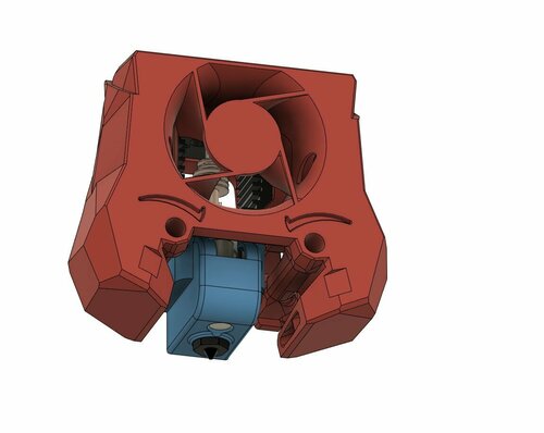
Stealthburner (RC1) Crazy Dragon Fan Duct
With special thanks to @chestwood96, sponsored by @3dmellow for the Crazy heatblock, as well as the awesome base design from the VoronDesign team, I'm able to create the Stealthburner Crazy Dragon fan duct.
The fan duct is designed based on the Rapido toolhead mount (RC1), retro-fitted with Dragon styled duct allowing wind to blow towards the throat only.
The duct is designed to be able to mount the Phaetus/Triangle Lab dragon heatsink with
Mellow Crazy Heatblock (verified by myself and @chestwood96) Phaetus Dragon UHF mini (standard UHF version without the melt zone extender) TriangleLab T Volcano (to be verified) Print Parameters
Print in standard Voron settings.
Previews
393 downloads
-
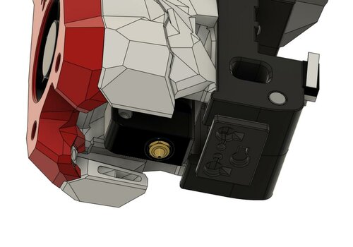
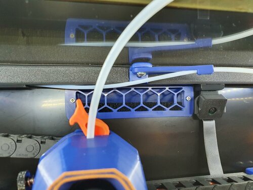
Bowden Tube Guide
PTFE Bowden Tube Guide and Canbus Wire Support
Required Hardware:
M3x8 Bolt and M3 T-nut M5x10 Bolt or a M5x8 Optional 4mm drill bit for cleaning out bowden tube path About
In my 350 build the PTFE tube kept getting caught so I made this arm to keep it up. The shorter arm works better so I recommend using it instead
Install
Drill out bowden guide with 4mm drill bit for a perfect fit (optional) Bolt mount to rear frame with M3x8 and tnut putting the lip at the top Screw arm on with M5x10 (I used a M5x8mm and it works fine) into the plastic allowing the arm to still be able to swivel1,454 downloads
-
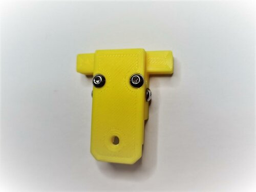
RunoutUnklicky
Runout UnKlicky Sensor
The Runout UnKlicky Sensor is a filament runout sensor that can be used to pause a print if printing filament breaks, runs out or otherwise is no longer present in the sensor.
The design uses magnets as the switch, making it easy and cheap to source BOM components.
Printing:
Components:
1x Pin.stl 1x Roller.stl 1x Base.stl (different options are available[*]) 1x Top.stl (different options are available[*]) Printer:
Use the Voron defaults and print in ABS or better The parts are orientated correctly in the STLs [*]Base and Top:
There are 3 bases and 4 tops to choose from:
Bases:
Base.stl is the standard base with push in holes for the PTFE tubes Base_PC4-M6.stl which allows the use of PC4-M6 connectors for the PTFE tubes Base_Collet.stl which allows the use of E3D M4 collets Tops:
Top.stl is the standard top with no mounting options Top_2020.stl provides mounting to 2020 extrusions using a t-nut Top_1515.stl provides mounting to 1515 extrusions using an inserted nut Top_1515_NoNut** provides mounting to 1515 extrusions if you have no inserted nuts available [**] The Top_1515_NoNut can be used if you don't have any free nuts. It snaps into the extrusion. If it moves or slips, you can use a M2x10mm self-tapping screw to secure the sensor to the extrusion. Do note that the screw can scratch the inside the extrusion if that might bother you.
BOM:
5x M3x8mm SHCS/BHCS (2x for the wired screws, 2x for the top/base, 1x for 2020 extrusion mount) 2x 6x3mm neodymium magnets (for the switch) 1x M2x10mm (optional for 1515 extrusion mount) 1x M3 Hammer T-Nut (for 2020 extrusion mount) 2x fork connectors (optional - for attaching wires) Assembly:
Parts used:
Insert one of the magnets into the pin, push it in fully so that it shows in the groove gap:
Insert the corresponding pin into the base and make sure that they attract from the outside as shown:
Insert the pin into the base with the pin grooves to the sides for the screws to enter. The pin should be pushed down to the bottom by the magnet in the base. Push the pin right up to the base magnet and screw in the screws to either side of the pin:
Place the top on the base and secure with two screws:
Attach cables to each screw that goes into the pin. There is no polarity and no voltage so it doesn't matter how they are connected. I used fork connectors for ease of use. Make sure the pin screws are screwed in tightly:
Hook up the wires to a multimeter and put it on it's continuity test. It should show resistance (and/or beep) when there's no filament in the sensor:
It should show no resistance (and/or remain silent) if you fully insert some filament into the sensor. Feed the filament through a few times from each side to ensure that you do not see any resistance when filament is present, and that you do see resistance when there is none:
Wiring:
Wire to an end-stop or similar pin. Do not connect to voltage, only to pin and GND. For example, with the BTT SKR MINI V2.0 you could use the E-STOP pin (PC15) and GND. For the BTT SKR Pico you could also use the E-STOP pin (gpio16) and GND.
Klipper:
A simple configuration is available in this repo. Upload and include runoutunklicky.cfg in your printer.cfg and change the PIN definition to the one you chose on your MCU. The config file contains what is required to use a runout sensor, but it will only literally pause the machine and resume when prompted. To have the toolhead parked away from the print to an accessible place to change filament, implement one of the following examples in your klipper configuration:
AndrewEllis93 Mainsail Test by inserting and removing filament. If it shows incorrectly in klipper add a ! in front of the PIN definition and test again.
Credits:
Thanks to:
chestwood96 for inspiration from the UnKlicky probe for SlideSwipe majarspeed for the Unklicky probe jlsa1 for the Klicky and Unklicky probes al3ph for the389 downloads
(0 reviews)0 comments
Submitted
.thumb.png.763b4453924800b636402ef582ec979f.png)
.thumb.jpg.455d15673ede3fd647f42b97864bbce2.jpg)
-
Most Actively Discussed Mods
-
Hottest Files!
.thumb.jpg.2c879d60315f8d86612bb06a137c204a.jpg)