-
TeamFDM.com is an UNOFFICIAL companion site for the DIY Voron 3D printer community. For official docs and final source of truth, visit the Official Voron Discord or the Voron Github
Printable Voron User Mods
Voron User Mods, or "UserMods", are a collection of community created and Team FDM curated modification for Voron Printers. All of these mods are available on the VoronUsers Github repo and unless otherwise specified follow the Voron communities GPL3.0 Licensing. Use any Mods at your own risk, if you make modification please share them on the VoronUsers repo.
Mod Authors: Have a Voron mod? Upload it at TeamFDM.com and let us know you're the author. We will ensure you can update and curate your files for more feedback! Please include tags for what Voron, or extruder your mod is compatible with.
652 files
-

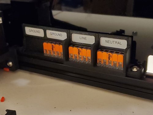
221-415 WAGO Mount with Labels (REMIX)
These are some WAGO 221-415 holders, which are just a remix of the WAGO holders in the Voron Github (here).
Since these models are designed to work with electrical components (WAGO blocks), use these models at your own risk.
The stock 2020 rail WAGO mounts included in the official Voron files fit the WAGO 221-415 blocks perfectly. So well that I had to break the first one I printed to remove the precious WAGO's, when I remixed the design, and needed them out, to test it. The models here are just modified from the original Voron design, I did not change the parts of the models which hold the WAGO blocks (since that works well).
There are really only 3 changes from the original design incorporated into this remix. The first change was to create a 4x415 block (as well as a 2x415 block). Then I added some taller walls between the WAGO's, and label holders. The walls are there to give connections a bit of extra protection from getting bumped. The last change is the label holders, which are designed to be used with Brother P-Touch 12mm labels, but other labels would also work if they can be made to fit. Since the labels may not stick well to a bumpy printed surface, they are retained by small frames which will slide over them. A dab of superglue could be used to hold the frames if there are no plans to change the labels.
There are three sizes and the label frames are the same between them (just print as many frames as needed). The design shown in the pics is the one I used in my Voron 2.4 R2 build, and is slightly different that the models here. But I only updated the design slightly, so that all the WAGO's have individual frames and higher walls between them in the models posted here (compared to the model I used which has two WAGO's sharing one label frame).
The STEP file is included for easy remixing.
You can check out some of my other projects in progress (and completed projects as well), on my blog here. I'm still building my Voron 2.4 R2 and am working on a few other designs related to it. If you want to help me get to my first spool of Prusament, you can add a make over at Printables for this design.
371 downloads
(0 reviews)0 comments
Updated
-
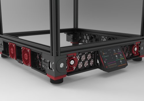
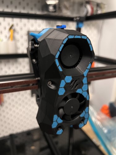
Hex mesh skirts for voron 2.4, with matching fan grills and Z motor covers.
Hex mesh skirts for Voron 2.4, with matching fan grills and Z motor covers. The skirts are obviously remixed versions of the default Voron designs. The fan grill and motor covers are my own creations.
The center, side, fan supports have been modified so that they fit onto the printer backwards. You will need to install one additional heat set insert into the front of the fan (4 total in the front), and add 3 to the back. Three m3x8 screws hold the fan into the support from the backside, and four m3x8 screws hold the fan grill onto the front.
Included is a model file for a 6020 fan blank. This blank will allow you to mount the grills on the side opposite that which has the fans, while maintaining the same appearance as the side with the fans.
For multi-color prints, just swap out your filament at the layer above the hex mesh.
I have included .stp files, to make it easier for anyone who would like to remix.
10,982 downloads
-
(0 reviews)
0 comments
Submitted
-
(0 reviews)
0 comments
Submitted
-
-
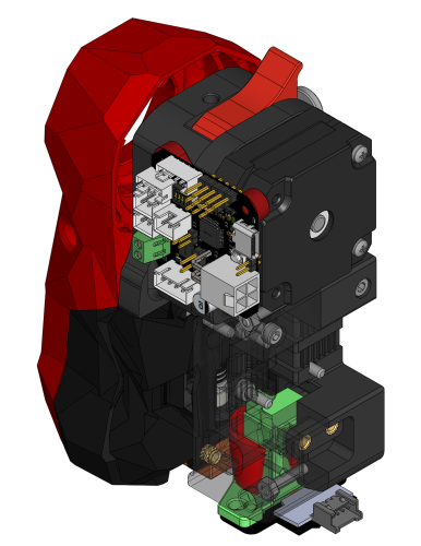
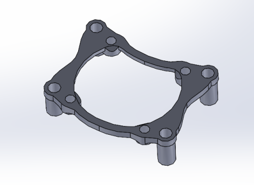
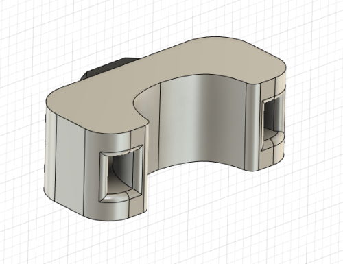
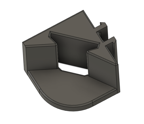
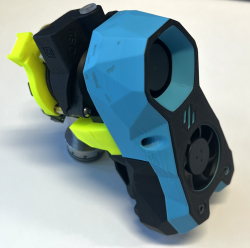
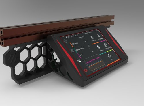
DRO Style, Side-Mounting, Housing for Official Raspberry Pi 7 inch Touchscreen
This is an "expert mod" and should only be attempted if you understand the risks involved, which include:
-ruining your printer's frame, which means starting over your project... The mod requires you to drill through your frame. I suppose the cable could be routed outside but, hey, in for a penny...
-dealing with RF interference on the usb lines which may produce hard to detect issues: The Raspberry Pi is going to be housed with the screen so the USB lines need to be passed back down in the cable to connect the main board and the webcam: care needs to be taken here to reduce RF interference so it involves wrapping wires in foil tape.
also, the actual print is challenging because it includes aspects of 'print-in-place' that require good temperature tuning to succeed: the cover is printed in place with the main case and need to be broken out with tools after printing. If you are good enough to drill your frame, I'm sure you'll figure out the print...
I doubt anyone will try this one but I'm putting it out there given the amount of work this was to perfect. So I could go on with details but I'll stop here. PM me if you want build this and have questions.
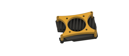
So for the uninitiated, a DRO is a computer you add to a machine tool to make it partly CNC and generally looks like this:
It is typically hanging around on the sides and most importantly, at eye level !
40mm x 10mm fan in fashionable brown 😉 snaps in tight
ADDITIONAL NOTES:
Wow, that's an honor, I hope you like it. Here is a bunch of extra info on that. did you look at the STL's ? what do you think of the print-in-place cover?
As it is now, the base piece is sized for my thick enclosure at 7mm. This can be adjusted:
Also, I did not test it yet because I'm waiting on parts to finish a bunch of peripheral stuff all at once when I put the printer out of commission. It should be next weekend. I'm pretty sure the Rpi will fit ok but I have a little doubt about the clearance between the fan and the pi's pins. I used drawings to figure out clearances but I may have did it a bit tight. The cover may need modifications but all the other parts are tested and working fine.
to separate the cover from the main body, you need to pry it from the inside from under the screw posts. if your print settings are just right, it pops off with moderate force. to do this, I placed the part in an open vice and pried with one of these:
drill size is 9/32" or 7mm or 7.5mm max. drill at high speed and low pressure to prevent sudden biting, take breaks to prevent melting of the drill guide
The cable I used is a leftover from industrial worksites. the passages are for a 7mm cable so anything smaller than that will work. you will need to splice usb cables somewhere in there so take care of adding shielding, especially where the cables pass near the z motors at the corner of the base
for the base: 2 x m3 t-nuts and 2 x m3-12 screws
for the arm and main body joints, 2 x m3-30 and 2 x m3-12
for the face: 4 x m3-8 and for the cover 2 x m3-12
also, the screen's included m2.5 brass posts are too long by almost 2mm and need to be replaced. -->testing needed but I got an assortment box:
https://www.amazon.ca/gp/product/B06XX28ZZR/ref=ppx_yo_dt_b_asin_title_o03_s00?ie=UTF8&psc=1
Finally got the time to get it working:
power management: I soldered on the monitor's PCB cause I had no space to plug on the header. I added 2 pairs of wires for the Pi and for the fan :
USB:
For cables, I just used 2 spare USB A-B cables from a dusty box. Try to get the thinnest possible wires that are shielded.
Here is a suitable choice for a spool of generic USB 2.0 shielded wire:
https://www.digikey.ca/en/products/detail/cnc-tech/2725-2828-BL-01000-A/6023708
Since the cable needed a splice in any case, I bought 'Type-A' USB connectors to make my own cable termination:
https://www.digikey.ca/en/products/detail/adam-tech/USB-AP-S-RA-SMT/9832307
Keep the wires as short as possible. I used a ferrule to join up the sheathings from both cables, which includes stainless steel, aluminum, copper, cotton and mylar... It can't be soldered !
Hot-Snot for that extra Chineseum touch also, I soldered a solid copper rod between the two connectors for strength. you can see it through the snot on the right side
As for the other ends of the cables, I just did a simple soldered splice with heat shrink: made them as short as possible, as straight as possible, and I introduced 1 turn between the data lines in the joint and shielded with foil tape.
RF shielding and hot-snot hider: it's just aluminum foil tape:
All working! looks awesome!
182 downloads
-
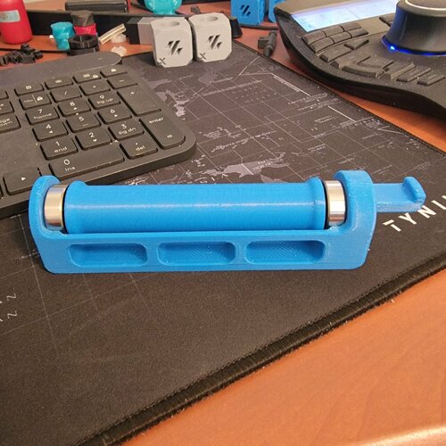
Roller Spool Holder for Switchwire
I designed this roller spool holder for the Switchwire after modifying and existing 2.4 roller spool holder to make it easier to print.
Roller (1 req'd) should be printed vertically. I chose gyroid infill as it doesn't cross over infill lines that've already been printed like cubic that can potentially knock the part off the print bed. Use standard Voron print specifications.
Pegs (2 req'd) for the ends should be printed vertically. I increased the perimeters to 6 so that I didn't need infill and also added a brim to further stabilize the parts during printing.
The Roller Holder (1 req'd) should be printed with the flat side down. You will need, at a minimum, supports for the hook and stub that mount into the Spool Holder Bracket. I used the default supports in SuperSlicer.
Bearings: Bearings are 8mm ID x 22mm OD x 7mm wide sealed ball bearings. Two required.
Spool Holder Bracket: This is the standard Voron Design spool holder bracket for the Switchwire. Print per Voron specifications.
777 downloads
- penatr8tor
- switchwire
- (and 2 more)
(0 reviews)0 comments
Updated
-
beacon CW1 Beacon drop-in mount
Made a drop in mount for anyone still using CW1. Not sure if it'll work with the CW2.
Requires the low profile beacon. The normal version will not work with this mount.
QTY: 2 - Brass heat insert from 2.4 BOM
My Beacon config
[beacon]
serial: [insert your address here]
x_offset: 0 # update with offset from nozzle on your machine
y_offset: 22.5 # update with offset from nozzle on your machine
backlash_comp: [change to whatever yours is]
mesh_main_direction: x
mesh_runs: 2
40 downloads
(0 reviews)0 comments
Updated
-
BTT CB1 Heatsink 30mm Fan Mount
I got some Heat issues on my CB1 so i desingt in Fusion 360 this Model
BOM
4 M3 Nuts
4 M3x12 screws to mount Fan on the Fan Mount
4 M3x20 screws to mount on CB1 and BTT M8P
40 downloads
(0 reviews)0 comments
Submitted
-
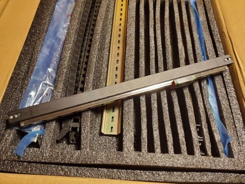
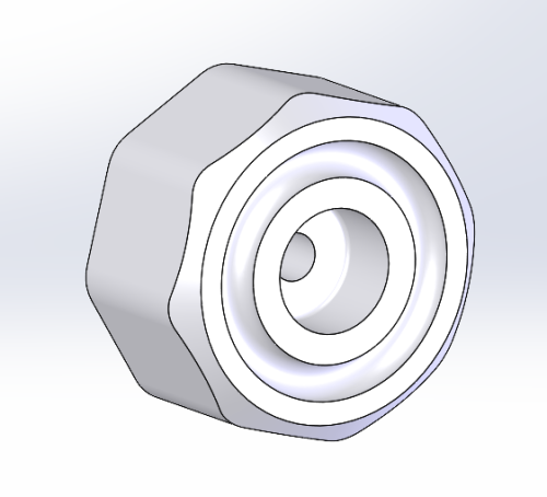
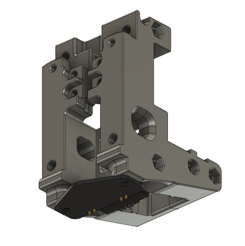
FYSETC Carbon Fiber Tube End Plugs and Rail Install Tools for the Voron 2.4 R2
These parts are designed to be used with a FYSETC Carbon Fiber X-Axis Tube, which I bought on sale at AliExpress for my Voron build, before realizing it would be a bit of a pain to assemble due to the design. These parts resolve most of the problems I expected to have, and went together well, when I built the XY joints and the X rail. I used the official models to help with the design and hole placements. Thanks to the Voron team for providing the design files and all their work in creating the Voron series of printers!
Before continuing, please note, use these parts at your own risk. They are by no means perfect and you can, if you wish remix this or use another method (STEP file is included). This worked for me and so I am posting it here, but I am still building my printer.
The parts include a model for an “plug” which holds three M5 locknuts and M5 washers, and two tools which are designed to assist with installing the MGN12 linear rail. The plugs stay in the final part.
Two plugs are needed and they can be interchanged between left and right sides of the rail. There are stops on the plugs, which I considered removing, however they help to keep them from going in too far during installation. I suggest printing one, and then testing it in the tube. If it is too tight, you can try calibrating the flow and then the horizontal expansion which will help get it to the correct size (the plugs should be 16.87mm in width). I printed them in PETG using a 0.6mm nozzle, 3 walls and 30% gyroid infill, since these should be robust. The plugs have holes designed within the parts, which are there to help fill up the areas around the nuts, since these areas need to be almost solid.
The tools are used by setting M3 locknuts in the pockets of the “A” tool, and then setting M4 washers on top (I used M4 instead of M3 since the M3 washers I have are too small to do much). Make sure the nuts fit snug but not tight, otherwise you will have a problem removing the tools.
I recommend doing a test before using the tool, by tightening down a few of the locknuts installed in the “A” tool, using some M3 screws, checking to see if doing so will cause the nuts to spin out. If they do spin out, DO NOT USE THE TOOL, since during installation there will not be a way to tighten the nuts down if they spin out. If the nuts do spin out in a test, then you can try adjusting the flow and horizontal expansion (if the holes are too large), or increase the strength of the part using more walls, more infill, higher temp, or use a different material. It is also possible that the nuts being used are different than the ones I used when designing this (the M3 locknuts I used were approx 5.42mm flat to flat, and the model is designed with 5.65mm flat to flat pockets).
Once tested, the “A” and “B” tools are then placed together, and both are then inserted into the tube and aligned with the holes for the linear rail. Note that the “B” model should have the groove facing the front of the tube where the rail will mount (this groove is there to allow the tool to pass by the screws when removed - see pics). If the tools go in too tightly, do not force them. Remove them, and either sand them down, or recalibrate flow and horizontal expansion for the material being used. Take the time to do this right, and if you don't feel this will work, please do not continue, since getting the nuts removed once installed will be a problem with or without a tool.
Once the tools are in place (and loaded with the locknuts and washers), the rail can be installed using M3x10mm screws (and M3x12mm screws on the holes that do not go through). I only printed one set, however if you want to print two sets, you can install screws on both ends of the rail at the same time, otherwise just do one side and then the other.
To remove the tools, use longer M3x12 screws in the holes that are not through holes, these will help to push the tool away from the nuts. I would start these longer screws with the “B” tool installed almost all the way, but remove the “B” tool before fully tightening the longer screws. If tightening down the M3x12 screws does not loosen the “A” tool enough to remove it, you can use a long (and thin) flat screwdriver, or even a folded over wire coat hanger to help pop it off the remaining nuts. It may also be easier to start with the innermost screws, remove the tools, reload and reposition, and then do the screws near the edges, if removing the tool is challenging.
Please refer to the pics to see how the tools work together, or ask a question in the comments.
As for whether it's worth it to use the FYSETC CF tube, I'm not sure yet. I forgot to weigh it before assembly, so I don't know how much is being saved, but it does seem pretty robust and I'm sure its lighter than the aluminum extrusion. The pic showing the weight of 438g is just the tube, rail, screws, nuts, washers and plugs as shown in the pics, it does not include any other parts like the printed XY joints. In any case, this is not an endorsement of the FYSETC product, only some parts which may help to actually use it.
The STEP file is included for easy remixing.
You can find more info and pics for this thing at my blog here. I'm also documenting my Voron 2.4 R2 build here (but it's been a slow going process due to some other issues).
83 downloads
(0 reviews)0 comments
Submitted
-
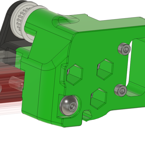
Belt Clip Shim for the CHAOTICLAB CNC Tool-free XY-Axis Tensioner for Voron 2.4
I'm building a Voron 2.4 R2 and purchased the CHAOTICLAB CNC Tool-free XY-Axis Tensioner for Voron 2.4, which is a nicely made part (milled from aluminum) with a knob to adjust the tension of the XY belts. Mine did not ship with any belt clips, and I don't think they are typically included, so I first tried using the stock clips. However when I assembled my XY axis, I found that the 30mm screws used to hold the XY tensioner to the Z-blocks were 2mm too long. This is because the CHAOTICLAB XY tensioner has a thickness of 3mm where it connects to the 2020 extrusion, while the stock is 5mm thick. Because this 2mm difference affects the stack height for the Z-carriage mounts, I thought I should do something about it. The simplest way to address this is to thicken the lower Z-belt clip (which is 5.6mm thick) by 2mm, so that's what this part does.
I included a version which adds 2mm (7.6mm overall), and another which adds 1.9mm (7.5mm overall).
I'm still building my printer, so things may change, but this seems like such a simple thing I doubt there will be any issues.
113 downloads
(0 reviews)0 comments
Submitted
-
Stealtburner CW2 Main Body and Latch UM2 MOD
Makes it possible to use a UM2 lock to hold your Bowden Tube in place, often it can let go when loading your filament manually, this fixes that.
127 downloads
(0 reviews)0 comments
Submitted
-
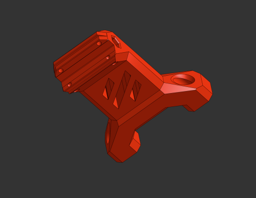
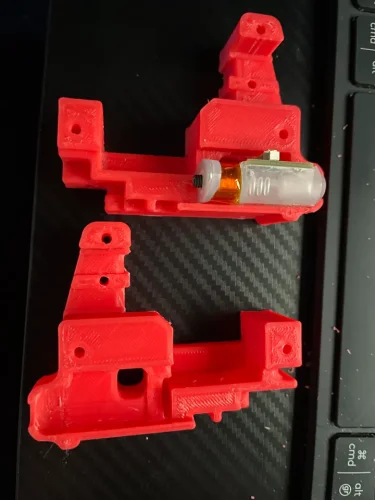
MGN 12 Y rail mod for Trident gantry
This mod allows you to use MGN 12 rails for the Y axis on your Trident Gantry. I think it will work on a 2.4 as well. All geometry is left stock except for the linear bearing mount. Enjoy
1,312 downloads
-
Voron foot with Oring
I didn't like any of the Voron feet I could find, so I made this one. No additional hardware required over stock, aside from a 4x20 oring to snap into the groove on the bottom. Adds just enough cushion, and anti-slip properties to the printer for my liking.
69 downloads
(0 reviews)0 comments
Submitted
-
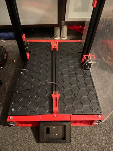
Deck Panel Lifting Handle - Trident with Inverted Electronics
It was a bit finicky to lift out the deck panel from my Trident with inverted electronics (awesome mod by the way). So I made this little handle up. It doesn't interfere with the bed at all. I used 3mm screws with locknuts so I don't get a rogue nut floating around with the electronics.
236 downloads
(0 reviews)0 comments
Submitted
-
CB1 Heatsink - 40mm Fan Mount
40mm fan mount for the BTT CB1 Heatsink. I suppose it would work without the heatsink as well, when slicing, just sink the part through the build plate far enough so that the standoffs are on the same plane. Uses Voron standard heatserts for mounting the fan. Uses stock heatsink screws to mount the part.
142 downloads
(0 reviews)0 comments
Updated
-
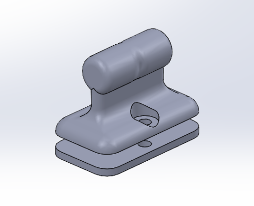
Cable Anchor - 2.5mm Ziptie
Trying to finish my Trident build, and can't get 1.8mm zipties for a reasonable price. I have a bunch of 2.5mm on hand, so I modified the original cable anchor to accept the larger zipties and also increased the saddle size a bit.
95 downloads
(0 reviews)0 comments
Updated
-
LED Strip Mount - 12mm - 2020 Extrusion
Modified Eddie's LED strip mount to accept a 12mm wide strip (rather than 10mm), and couple small changes in order to be printed with 0.6mm nozzle.
74 downloads
(0 reviews)0 comments
Updated
-
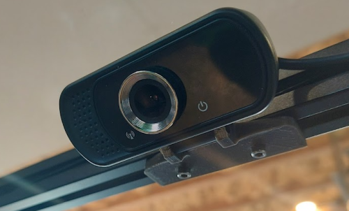
Voron Cam Mount - Amazon Camera
Needed a camera mount for the amazon camera I got for my Trident. I couldn't find one anywhere, then miraculously, I go to upload this and see that user jbisson9 had uploaded one I could've used https://www.teamfdm.com/files/file/677-amazon-cam-holder/, but couldn't find it at the time. Anyway, here's another! Width between the ears is 16.2 mm (camera is 16mm). Wish the camera was a little bit wider FOV (350mm bed in picture).
Camera Link:https://www.amazon.ca/dp/B07VL7BNLZ?psc=1&ref=ppx_yo2ov_dt_b_product_details
Remixed from TAKUYA's design: https://mods.vorondesign.com/detail/FtQ8kWIGoBhnVjtAyGCPJA
63 downloads
(0 reviews)0 comments
Submitted
-
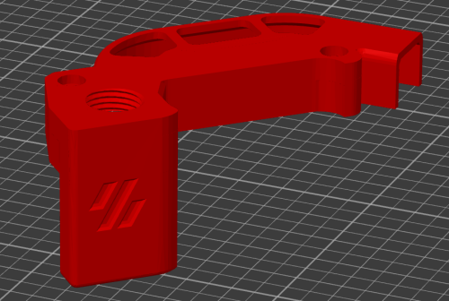
Switchwire CW2 Beacon probe mount
I've made a mount for the Beacon3D probe for a CW2 Switchwire
I used the normal version beacon probe
Mount has been tested and works great, here is a youtube short of it in action
*** I've added a second mount as that moved the probe 2mm further away I wasn't happy with the original mount because as soon as the carriage got a bit melted the probe would start touching the heat block. I also believe because the probe is so close to the heater it causes the mount the deform.
883 downloads
- switchwire
- clockwork2
- (and 3 more)
-
Umbilical Cable Cover remix
In the midst of another V2.4 350mm build I am going to try and use CAN bus on this one before converting my other v2.4s over. I still wanted to use the Hall Effect end stops so have 4 wires running from the gantry. this is a remix of the standard cable cover and the umbilical connection with a cable gland fitting.
69 downloads
(0 reviews)0 comments
Submitted
-
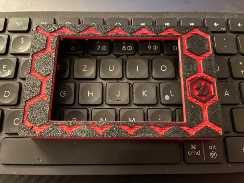
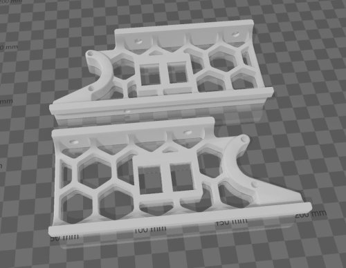
Keystone Front Skirt for Voron V2.4 350
Front Skirts with Keystone Opening for Voron V2.4 350
125 downloads
-
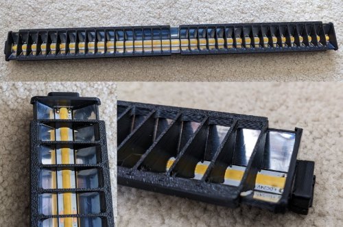
Low Glare Modular COB Chamber Lighting with Snap in Installation
Maniac-Chamber-Lighting
This project uses 24V high efficiency white COB LED strip lighting to provide low glare interior lighting on a Voron 2.4 350/300/250.
One of the goals of this project is to simplify installation of lighting with snap in mounting brackets and pre-assembled wiring and junction boxes, and eliminate the use of screws. The commonly available adhesive backed 24V COB strips are cut to size and attached to each printed LEDBar. Length of strips will be a multiple of 50mm.
Aluminized Mylar tape attached to the LEDBar forms a corner reflector to improve light output. A combination of light baffles/diffusers on the side strips along with installation angle of the front and rear LEDBars prevents glare as the COB elements themselves are not directly visible when viewed from the front of the Voron. The lights are connected to a PWM MCU output that can be connected to a Klipper input button or Mainsail dimmer slider.
The LEDBars are designed to just fit along the top frame rails and include a 2mm JST connectors for easy installation and removal while servicing the printer. Printed brackets "permanently" snap into the 2020 and the LEDBars in tern snap into these brackets making for quick removal of the LEDBars as needed.
Printed zero clearance slot covers snap into the vertical 2020 extrusions and make for clean installation and wire management.
A printed TPU Z belt cover snaps into the 2020, making the wire run from the vertical 2020 section to the electronics bay non-exposed. A complete set of TPU parts to seal and support the base panel will be published later.
The design was prototyped on a Voron 350, but STL and STEP files are included for 300 and 250 printers. The LEDBars must be printed at a 45 degree angle to fit on the build plate. Double check that you can fit the LEDBar on your build plate before committing to the project and ordering parts. Set the infill angle to 0 degrees for the LEDBars.
BOM
Qty Item Comment 2m 24V COB strip; 50mm segments; adhesive backed https://www.amazon.com/gp/product/B0B9SFMZ1L 1 roll Aluminized Mylar Tape 1/2" (12.7mm) https://www.amazon.com/gp/product/B07TYKFS8K 10ft/3m Red 26awg PTFE stranded wire less than $0.15/foot ebay/Amazon/AliExpress 10ft/3m Black 26awg PTFE stranded wire less than $0.15/foot ebay/Amazon/AliExpress 4 JST 2.0 4-Pin Male Connector plug with Wire + Female Connector plug(have not cable) https://www.amazon.com/gp/product/B01DUC1S7S 2 gray 20 awg crimp terminals Ferrule Crimping Tool Kit, Preciva AWG23-7 with 1200PCS Wire Terminals Crimping Connectors Wire End Ferrules https://www.amazon.com/gp/product/B073TZ5BBG - solder, rosin flux
Printer Tuning
Print STL/Tools/Test.stl.
Measure the width of the 5mm arms at the two points indicated and verify they are within 0.05mm. Measure the length of the arms to be 100mm to be within 0.10mm. Check for no elephant foot. If everything looks good, print the STL/Common/LEDBar50.stl. Insert a Female JST plug and test fit the STL/Common/LEDRetainer.stl. Otherwise follow the tuning suggestions below
Test print width and length adjustment
The width of the 5mm section of the test print is primarily influenced by the slicer's filament extrusion multiplier. To dial it in, do two test prints with different extrusion multipliers and linearly interpolate between the two to determine the correct setting.
The 100mm length is primarily influenced by the filament shrinkage factor. Again, do two prints and linearly interpolate.
There is some interaction between the two settings so it may require some iteration.
Test print varying 5mm thickness
If the two 5mm width measurements differ, and assuming Pressure Advance is dialed in, chances are the difference is caused by temperature flow variation.
(Theory)- In the same way Pressure Advance has to build up pressure at the beginning of a new extrusion to control print width, there is a secondary factor that the extrusion pressure builds slightly on long high flow rate lines because the extrusion temperature of the melt decreases. At high flow rates, the filament has less time to reach full temperature compared to printing slowly. This effect is very pronounced with TPU but also observed with ABS. The net effect is over extrusion once the flow rate decreases as in the case of a 90 degree turn. Pressure advance does attempt to decrease pressure when decelerating but it does not take into account the pressure increase due the temperature drop and the increased flow as the temperature returns to a normal level with the flow decreases... bottom line don't use the 30-second Benchy settings - try decreasing the peak flow rate/print speed to minimize the effect.
Elephant Foot
After getting the flow rate dialed in, remove any remaining elephant foot by decreasing the flow rate of the first layer or re-adjust the z-offset to increase the first layer height.
Printed Parts
Print after calibration:
Common Printed Parts
[alt] CornerJunctionBox.stl -left rear & right front [x2] CornerJunctionBoxMirror.stl -left front & right rear recommended [x4] CornerJunctionCapLarge.stl [x4] CornerJunctionCapSmall.stl [x3] LEDClip15.stl -front [x9] LEDClip45.stl -side & rear [x4] LEDRetainer.stl [4x-ABS] Z Belt Cover Retainer.stl *** Test print first TPU part and trial fit before printing others Shore 95 TPU *** [x1-TPU] DeckCornerLeftFront.stl [x1-TPU] DeckCornerLeftRear.stl [x1-TPU] DeckCornerRightFront.stl [x1-TPU] DeckCornerRightRear.stl
Voron 350
[x2] LEDBar350.stl -set infill angle to 0 deg [x2] LEDBar400.stl -set infill angle to 0 deg [x4] LEDdiffuser350.stl -check for gaps in 1st layer; might need to reduce infill line width 140%=>120% [x4] LEDdiffuser400.stl -check for gaps in 1st layer; might need to reduce infill line width 140%=>120% [x2] SlotCoverVert200.stl [x2] SlotCoverVert287.stl
Voron 300
[x2] LEDBar300.stl -set infill angle to 0 deg [x2] LEDBar350.stl -set infill angle to 0 deg [x4] LEDdiffuser300.stl -check for gaps in 1st layer; might need to reduce infill line width 140%=>120% [x4] LEDdiffuser350.stl -check for gaps in 1st layer; might need to reduce infill line width 140%=>120% [x2] SlotCoverVert200.stl [x2] SlotCoverVert237.stl
Voron 250
[x2] LEDBar250.stl -set infill angle to 0 deg [x2] LEDBar300.stl -set infill angle to 0 deg [x4] LEDdiffuser250.stl -check for gaps in 1st layer; might need to reduce infill line width 140%=>120% [x4] LEDdiffuser300.stl -check for gaps in 1st layer; might need to reduce infill line width 140%=>120% [x2] SlotCoverVert200.stl [x2] SlotCoverVert187.stl
Assembly
LED Bar
Precisely cut a section of the COB strip to match the length of the LEDBar using a sharp razor. The LEDBar400 uses a strip with 8 50mm sections.
Identify the end of the strip with the correct +/- orientation and scrape/abraid any oxide or coatings from the contacts using fine sand paper or razor until clean copper is exposed.
Tin the contacts and wipe away any excess solder with a paper towel or solder wick. https://github.com/VoronManiac/Maniac-Chamber-Lighting/raw/main/Image/TinnedCOB.jpg?raw=true
Remove the center two pins of the female JST connector. They'll slip out of the PCB side of the connector with enough force. Tin the remaining two pins.
Place the LEDBar into a small tool vise if available to help hold things in place. This helps immensely.
Test fit the JST connector into the LEDBar. Test fit the LEDRetainer by placing it over the connector and pressing it into place (it will need to be removed so don't force it). Dry fit the COB strip under the connector and note the alignment of the tinned pads and the connector pins. Check that that there is enough room for the un-tinned end of the COB strip to lay flat.
Remove the middle wires on the male JST connector using an Exacto to pry up the retaining tabs on the JST plastic housing. Swap wires as needed to have Red on the "+" pin and Black on the "-" pin
Remove the LEDRetainer, and male & female connectors. Apply Aluminized Mylar tape strips. Position the tape at the edge of the LEDBar. Starting a few inches in, begin pressing the tape in place, working to the end of the LEDBar. Crease the tape into the corner with a toothpick and trip off the excess. https://github.com/VoronManiac/Maniac-Chamber-Lighting/raw/main/Image/PXL_20230326_192127167.jpg?raw=true https://github.com/VoronManiac/Maniac-Chamber-Lighting/raw/main/Image/PXL_20230326_192234882.jpg?raw=true
Peel back sections of the protective COB strip backing and incrementally attach the COB strip, centering it between the Mylar strips. The COB strip should be positioned so it starts exactly next to the raised bar on the print. The LEDBar is ~2mm longer than the strip, so when the COB is installed, the un-tinned end of the COB strip should not hit the far end of the LEDBar. Once attached, run a blunt soft object like a popsicle stick or round edge of a credit card along the white COB strip edges to firmly seat it. Re-install the female JST connector and LEDRetainer. Solder the JST connector to the COB strip. Connect to 24V supply and test COB. https://github.com/VoronManiac/Maniac-Chamber-Lighting/raw/main/Image/PXL_20230327_052607121a.jpg?raw=true
Junction Boxes
The junction boxes snap into the upper rails at opposite corners of the printer. Each junction box services two LEDBar's and feeds wires down the 2020 vertical rail. The junction boxes can be removed by gently prying them from the frame until each end of the box pops out of the 2020. With a little care, breaking the snap tabs is not an issue.
A pair of red/black wires runs from each junction box into the MCU board in electronics bay. A "Y" splitter joins the front and back LED feeds for final connection to the MCU. The required length of the wires will be dependent on the machine size, electronics bay wire routing path and location of the MCU. For a typical Voron 350, 1.7m and 1.1m wire lengths seem to work. When figuring the required length, add in and extra 10% that will be taken up when the wires are twisted together.
Be sure the two center terminals and wires from each connector have been removed by prying up the retaining tabs on the connector with an Exacto to free the wires. Re-insert wires as desired to have the Red wire match up with the "+24VDC" pin on the LEDBar and a Black lead match up with the "-".
Cut the wires of two male JST connectors to 112mm and strip 8mm of insulation off each end.
Remove 8mm of insulation from the ends of the PTFE wires.
Twist the bare red wires from the two connectors and PTFE wire together and insert into a gray 20 awg crip terminal and crimp. Twist and crimp the black wires in a second crimp connector. https://github.com/VoronManiac/Maniac-Chamber-Lighting/raw/main/Image/PXL_20230324_170353732.jpg?raw=true
Insert crimp into junction box and route red wires as shown below https://github.com/VoronManiac/Maniac-Chamber-Lighting/raw/main/Image/PXL_20230324_173040693.jpg?raw=true
Insert crimp into junction box and route black wires as shown below https://github.com/VoronManiac/Maniac-Chamber-Lighting/raw/main/Image/PXL_20230324_173913668a.jpg?raw=true
Install large and small snap in covers. With junction box is a vise, place a piece of tape on the far end of the red/black wires and insert into drill and create a twisted pair. To help keep wires from untwisting, pass the twisted pair around a round object like a pencil along the length of the wires. This helps wires take a new set.
https://github.com/VoronManiac/Maniac-Chamber-Lighting/raw/main/Image/PXL_20230324_175535253.jpg?raw=true
Installation
Snap a junction box into the top frame.
The slot covers are split into two sections to ease installation. Lower the Gantry and install the top slot cover.
Starting at one end, gently push the slot cover into place being careful not to pinch the wires. Applying a slight tension to the wires keeps them inside the slot cover. Once the slot cover is fully pressed into place, the slot cover will side in the 2020 channel with minimimal effort. The wires should free loose when jiggled. https://github.com/VoronManiac/Maniac-Chamber-Lighting/raw/main/Image/PXL_20230327_053830500.jpg?raw=true
Raise the gantry. Slide the top slot cover upwards as needed and install the lower slot cover. https://github.com/VoronManiac/Maniac-Chamber-Lighting/raw/main/Image/PXL_20230327_055426979.jpg?raw=true
Bend TPU Z cover open and slide Z belts into slots. Press far side into 2020 channel.
Some of the pictures below were taken on a new Voron that did not have the Z belts installed yet. For an existing machine there is no need to remove the Zbelts to install the Z belt Covers
Position the twisted pair so it is clear of the remaining TPU tab and gently press the it into the 2020. Use a small screw driver to to guide the wires and keep them from pinching. between the tab and the 2020. An allen wrench provides a convenient lever for removing the TPU tabs from the 2020. The TPU can also be removed by wedging a small screw driver between the 2020 and the TPU. https://github.com/VoronManiac/Maniac-Chamber-Lighting/raw/main/Image/PXL_20230327_055824980.jpg?raw=true https://github.com/VoronManiac/Maniac-Chamber-Lighting/raw/main/Image/PXL_20230327_060104321.jpg?raw=true https://github.com/VoronManiac/Maniac-Chamber-Lighting/raw/main/Image/PXL_20230327_060431409.jpg?raw=true
Snap the Z Belt Cover Retainer(s) in place to hold the Acrylic deck panel against each Z belt cover. https://github.com/VoronManiac/Maniac-Chamber-Lighting/raw/main/Image/PXL_20230328_041948365.jpg?raw=true
Snap diffusers and 45 degree mounting clips on the side LEDBar's to test fit. The mounting clip ends easily unsnap by pressing them over the lip of the LEDBar.
https://github.com/VoronManiac/Maniac-Chamber-Lighting/raw/main/Image/PXL_20230327_151505688.jpg?raw=true
Plug the JST connector into the LEDBar. For initial installation of the LEDClip15, they can be inserted into the 2020 one by one and slid into position, or the entire LEDBar can be snapped in as a unit. Not necessary, but the diffusers can be locked into place so it doesn't slide with a drop of CA.
Installed LEDBar https://github.com/VoronManiac/Maniac-Chamber-Lighting/raw/main/Image/PXL_20230328_043655822.jpg?raw=true
TO DO
update pics add on/off/dim switch & macros publish Lower Panel Deck TPU seals & retainers publish TPU Side/Top/Rear Panel & Front door seals, Retainers & hinges publish Maniac-Aire HEPA/Charcoal filters publish Maniac-Drybox
1,490 downloads
-
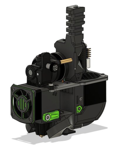
Stealth Orbiter V2.0
StealthOrbiter
This mod aims to mount the orbiter V2.0 extruder to the stealthburner assembly. In addition, it incorporates the Orbiter filament sensor to enable support for the ERCF.
There are a number of different versions, depending on your configuration:
Standard mount Standard mount, with PG7 cable gland Filament sensor mount Filament sensor mount, with PG7 cable gland The most up to date files can be found on the github repo
Acknowledgments
- spacelab_2021, for providing the starting point I used in developing this mod
783 downloads
-
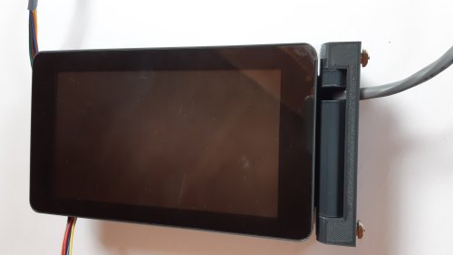
Touch Screen housing for BigTreeTech TFT35 SPI V2.1, Fits Voron 0.2
The screen is held in via 4 m3x8 socket head cap screws, which go into the housing from the back and thread into the bezel. The bezel is secured over the accents with a couple drops of super glue.
The only two required supports are integral to the model and "print-in-place". They will need to be removed after the print is finished.
I tried to design this so that it would require minimal supports, but the honeycomb pattern has some fairly long bridges. Depending on your printer's overhang and bridging performance, you may need additional supports. Prusa Slicer's organic supports set to 30* worked very well for me on a similar design.
329 downloads
-
Most Actively Discussed Mods
-
Hottest Files!
.thumb.jpg.2c879d60315f8d86612bb06a137c204a.jpg)