-
TeamFDM.com is an UNOFFICIAL companion site for the DIY Voron 3D printer community. For official docs and final source of truth, visit the Official Voron Discord or the Voron Github
Printable Voron User Mods
Voron User Mods, or "UserMods", are a collection of community created and Team FDM curated modification for Voron Printers. All of these mods are available on the VoronUsers Github repo and unless otherwise specified follow the Voron communities GPL3.0 Licensing. Use any Mods at your own risk, if you make modification please share them on the VoronUsers repo.
Mod Authors: Have a Voron mod? Upload it at TeamFDM.com and let us know you're the author. We will ensure you can update and curate your files for more feedback! Please include tags for what Voron, or extruder your mod is compatible with.
652 files
-

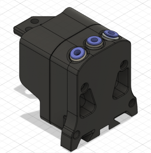
Afterburner - Triple Bowden
This is a remix of the Dual Bowden but for filaments/extruders. M4 is the recommended extruder.
126 downloads
- afterburner
- bowden
- (and 1 more)
(0 reviews)0 comments
Submitted
-
(0 reviews)
0 comments
Submitted
-
(0 reviews)
0 comments
Submitted
-
(0 reviews)
0 comments
Submitted
-
V0 Bed Wagos
Attach Wago 221-412 to your v0 bed.
I wanted a way to bridge the bed fuse, without using a semi-permanent connector.
Easy to install. Just pop Front_Bed_Mount_x1.STL off the front of your bed, slide in some nuts, slip on the wago mount and you're all done.
Prints fine, I'm sure the design could be improved upon. Especially, the 2x. I got lazy there.
41 downloads
(0 reviews)0 comments
Updated
-
Plug Panel Mod for Schaffner FN286-10-06
Connection panel for Voron 2.4. Suitable for Schaffner FN286-10-06 and 2x LAN / USB Keystone sockets.
22 downloads
(0 reviews)0 comments
Submitted
-
V0 Skirt
Simple edit of the Standard skirts for the V0. Screw holes have the standard spacing.
9 downloads
(0 reviews)0 comments
Submitted
-
Voron V0 SSR Mount
BOM:
2 x M3x8 (to fix to the 1515 extrusion, the nuts are from the assembly instruction already available, instead of the 5V power supply)
2 x M4x12 (for the SSR to the bracket)
2 x M4 nuts
14 downloads
(0 reviews)0 comments
Submitted
-
Voron V0 Mean Well Power Supply Bracket (Funssor Kit)
This bracket works for the panel kit from Funssor from AliExpress, which has already some holes on the bottom bracket.
"Funssor upgrade Voron 0 V 0,1 acryl pannel kit für Voron 0,1 3D drucker DIY kit" https://de.aliexpress.com/item/1005002596904062.html
BOM:
3 x M3x5 heat inserts
3 x M3x6 (for the bracket to the panel)
2 x M3x3.5 (for the power supply to the bracket)
15 downloads
(0 reviews)0 comments
Submitted
-
Duet 2 WiFi Mounting Bracket with and without RPi
BOM:
6 x M3x12
4 x M3x5 heat inserts (should also work with the 4 mm heat inserts)
for the RPi:
4 x M2.5x89 downloads
(0 reviews)0 comments
Submitted
-
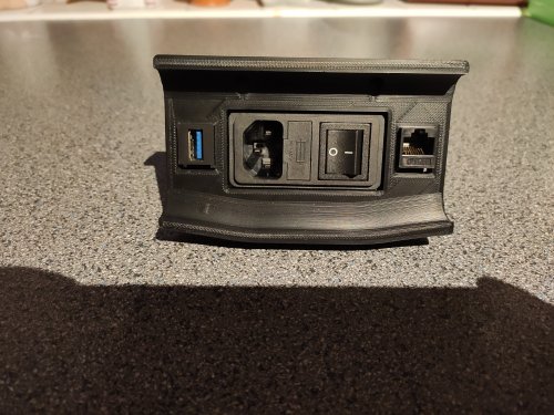
Mains Plug_Panel for RND 165-00057
This is a modified plug panel designed to be used with the RND 165-00057 mains filter with integrated switch sold by Reichelt, Distrelec or ELFA For Version 2.4.
2 downloads
(0 reviews)0 comments
Submitted
-
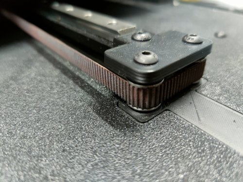
VoronSW 9mm Belt Mod
BOM:
2x M5x25 BHCS 2x M5x30 BHCS 1x M3x25 SHCS 8x M5x1 Spacer 8x F695 Bearing with flange (from the SW BOM) 4x 695 2RS 5x13x4 Bearing without flange 1x GT2 20T Pulley (5mm B, 9mm W) 1x 1m GT2 Belt (9mm W) 3x M3 Heat inserts (from the SW BOM) Slicer Settings:
Mainly this should be printed with the Voron PIF settings (4P, 40% Infill etc.) But i recommend to print the panels and "Motor Top Mount" with 100% infill. The panels will bent less and the section of the motor mount where you screw it to the 2020 extrusion is more stable. Notes regarding the Belt Anchor:
The limit switch is only held by one screw instead of two screws like in the original design, otherwise the screw would hit the belt. Notes regarding the Deckpanels:
For the "Bottom Y Idler" you will need 2 small cutouts on your panels (see pictures). You can drill it out, or print the panels. The files for the panels are orientated like the name of the files. If you want a nice finish i recommend to flip them upside down in slicer and print on a textured pei sheet. If you want a smooth finish you can try "ironing" the toplayer, then leave the files at the current orientation. You can glue the panels together where the front and back snaps together if you want. I just pushed them together and didnt glue them, works great and sits tight. Lay both on a flat surface, snap them together and press with something heavy at the connection points. The panels also tend to bent at cooldown after printing, a good tip is to remove the panel with the pei sheet from the printbed immediately(!) after printing and quickly place it on a flat surface (for example on the floor), then quickly place a thick book on top and weigh it down properly. I just stood on it for 10 minutes, worked great. This step is important, otherwise the panel will bent and the belt anchor will hit the panel when traveling.281 downloads
(0 reviews)0 comments
Submitted
-
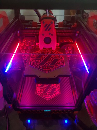
Voron Parts Logo for your VORON V0.1
STL File
You can print this logo on your 3D printer. I have included base (0.6mm thick) in this stl file which you can print in base color (three 0.2mm layers) & change filament after 3 or 4 layers to your accent color. I changed filament after 4 layers. Use monotonic top layer infill to have uniform top layer of Black base. Check images below. Use VHB tape to stick it to deck panel.
As this is very small logo (height is 115mm), printing with smaller nozzle will add more details. I have printed this with 0.4mm nozzle as shown in below images.
Image Files
Image files are included in high quality JPG & PNG format if anyone wants to print them on paper with traditional ink printer.
92 downloads
(0 reviews)0 comments
Submitted
-
V0 Skirts with Integrated Zip-Tie Points
This is a pretty simple mod that adds a series of small loops along the top of the V0 skirts that you can use to zip tie cables to.
These skirts also have an access hole added for tightening the middle M3 screw.
0 downloads
(0 reviews)0 comments
Submitted
-
Fysetc S6 V2 Mount
This is a mount for the Fysetc S6 V2 board that is intended to be used with the V2 PCB DIN mount brackets and should work with any machine with DIN rails. To use this, print the mount and two of the V2 PCB DIN mounts. Attach the PCB DIN mounts using M2 self tapping screws. Attach the Fysetc S6 to the mount using M3 hardware of your choice. I used 6mm M3 hardware, but 8mm should work fine.
This mount was designed and tested with the Fysetc S6 V2.0 board, but likely works with the S6 1.2 and F6 boards, since they're documented to have the same footprint.
1 download
(0 reviews)0 comments
Submitted
-
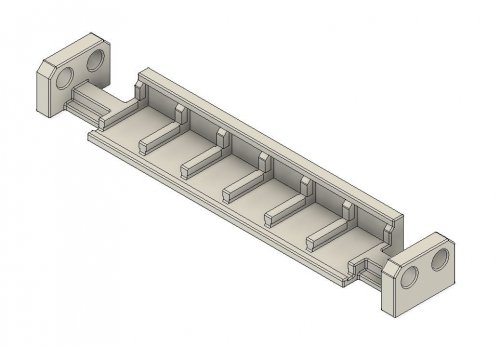
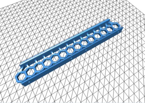
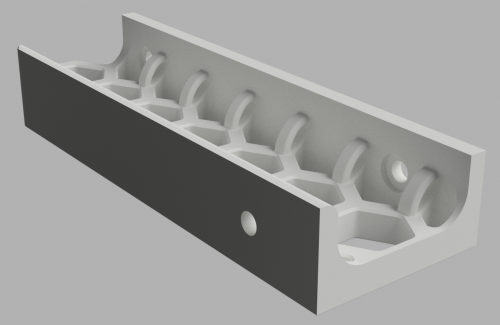
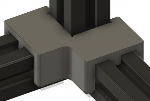
Voron 2.4 Extrusion Jig
What is this?
This model is a simple jig to help align the bottom extrusions to each other and the vertical extrusion. This helps keep everything square when assembling the frame.
How do I use it?
It's recommended you print four of these, although just printing one is still pretty helpful. Either way, assemble the frame as described in the manual, but instead of tightening down the screws, leave a little bit of slack so they can still move a little bit. Once you have done that, clip the jig on to the vertical extrusion and slide it down over the two horizontal extrusions. Once you've done all four corners, tighten each side, keeping each corner as flat as possible while doing so.
How should I print this?
Same as any other Voron part. I printed this in eSUN ABS+, but any ABS will likely work. I can't speak for PLA or PETG.
NOTE
How useful this part is will depend a lot on how well calibrated your printer is. This part should be fairly snug, but not require significant force to put in place or remove. If you find it's very tight or loose then it will probably not be useful for you.
244 downloads
(0 reviews)0 comments
Submitted
-
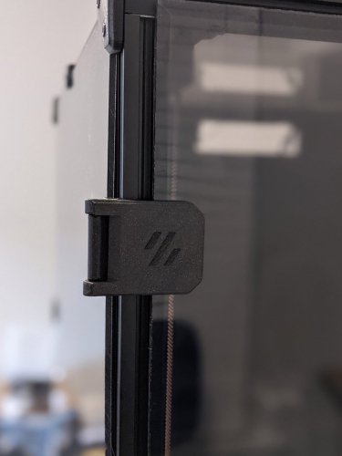
270° Hinge - Parametric
These hinges allow for 270 degrees of motion, from closed 0° to 270° full open parallel with the side panels. This was developed out of an effort of running into tolerance issues with the spec hinges not allowing much room if the two panel doors are used and are slightly cut larger by only 1 mm or so. I ran into issues closing and the doors hitting and needed something that allowed more horizontal movement.
So it was decided to figure a way to mount on the side of the printer. After some searching, printing, trial & error, I came to what you see below. 270 degrees wasn't the initial intention but figured if they are going to be mounted to the side, might as well take advantage of the extra flexibility.
During development and testing of these I struggled with tape being sufficient with my first version of these. So went back and designed these to use hardware and remove tape from the equation. Hardware mount was heavily influenced by Randell other door hinge mod that uses hardware. The handles in this mod are a remixed version of Randell's to adjust for the altered latch developed for this setup. The latch in the mod gives as much room as possible vertically if panels are slightly too tall.
Note: Un-tested but the holes should line up with Randell's hardware for the hinges if you are looking to swap for more swivel.
As you can see this setup allows vertical and horizontal freedom if your panels are cut too large.
BOM
Hinge Hardware
M3 x 35 mm SHCS [x4] M3 x 8 mm SHCS [x4] Side Mount M3 x 8 mm BHCS [x8] Backplate. SHCS can also be used here. And if you want a flush look 8 mm FHCS M3 Threaded Insert [x8] M3 T-nuts [x4] hammerhead or spring ball, your choice Latch
3 mm x 6 mm magnets [x4] M3 x 6 mm SHCS [x2] BHCS screws work better here if you have them M3 T-nuts [x2] hammerhead or spring ball, your choice Handles
3 mm x 6 mm magnets [x4] M3 x 6 mm BHCS [x8] M3 Threaded Insert [x8] Printing
Use the default recommended for Voron parts. Can be done in PLA but I have not tested this. If having issues printing side mounts you may need to add a brim to those and trim before installation
Layer Height : 0.2 mm Extrusion Width : 0.4 mm Infill : 40 % Walls : 4 Solid Top/Bottom : 5 There is a left (a) and right (b), you will need to print 2 for each side. There are 2 versions of each of the hinge faces if you don't want a Voron logo or want to mix and match. Multiple depths are also provided. Should you need a specific depth and no access to Fusion, feel free to reach out to me on discord chrisrgonzales#0731 The 4 mm is typical 3 mm panel and 1 mm foam , and 6 mm files are for 3 mm panel and 3 mm foam.
You will need to print 4 of the side mounts, they are not side specific.
Assembly
These are designed to have a tight tolerance, so the 35 mm screw can be screwed into the lower portion of the face hinge, and still have some play without wiggle. You will likely have to thread it all the way down then play with the hinge and pivot it a couple of times to work it in before attaching. Do not over tighten the screw as it will bind on the upper portion. If you feel it binding, back the screw off just a lil bit.
When installing back plates to hinges to protect panel from cracking be careful not to screw down too much as insert depth is shallow as you may risk of pushing through. The backplates have a chamfer for more recessed look, but can be flipped if you have longer hardware.
Take it slow when installing heat inserts as it's very easy to push them through and cause deformation on the face of the hinge. Set temp on iron lower than used on most other heat inserted parts as this gives you more time not to press through. Also you may have to use the side of your iron's tip as not to puncture all the way.
For placement of drilling, you can install the hinges in place, and tape or use panel clips from sides temporarily to hold front doors and tape outline of hinge. Then remove the panel and hinge, place the hinge where the tape outline is, mark the hole and drill.
CAD Files
The CAD files are parametric! When opened in Fusion 360, editing the thickness parameter will change the spacing and geometry to allow the hinge full 270 articulation. Enter in thickness of your panel and foam, I would recommend accounting for the compression in your foam. Example 3 mm panel with 3 mm foam, typical 6 mm would be entered, but possible that 5.8 mm might be a better choice to give some compression for a seal. If you are unsure, printing a single bracket and testing fitment and offset would be ideal.
If you would like to use this with tape only you may adjust the faceThickness parameter to be thinner but wouldn't suggest going smaller than 3 mm. You will also need to remove or extrude flush the holes for the brass inserts. Also the faceWidth parameter may be adjusted to be smaller width. Would not go lower than 27 mm for this parameter.
The logo can be removed if needed. If using Fusion 360 with history, step back two actions and logo will be removed. Otherwise removal of chamfer and extrude flush will be needed.
thickness : panel + foam depth in mm (default 4 mm) faceThickness : depth of the face portion of hinge not including panel + foam (default 5 mm) FacePlate_width : width of facing hinge from edge of extrusion to the opposite edge. Not actual width of hinge default (34.9 mm) Taped versions use 27mm. See image below. Questions / Suggestions
If you have any questions or suggestions feel free to contact me on Discord chrisrgonzales#0731
29,598 downloads
-
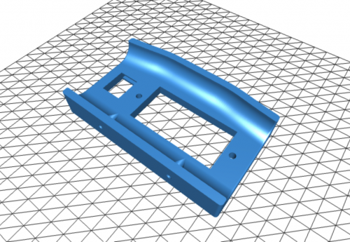
V0 Handles Slim
My V0 is in my garage and my shop in the other room. Moving it back and forth for repairs was a pain as the V0.1 has no real place to grab it.
And so I made handles that don't protrude much from the sides (16mm) of the tophat keeping the footprint as close to stock as possible.
To mount:
4x M3x12 (8 for both sides) 3x M3 Nut (6 for both sides) Print two of the file that fits your side panel thickness
2.5mm 3mm You will have to add 3 nuts to the top extrusions as the handle replaces the top panel clip and requires 4 nuts (3 new + 1 old from panel clip)
Remove the middle clip on the top extrusions but keep the nut in place. Unscrew both screws that hold the top right and left extrusions in place. Lift the extrusions just enough to be able to add 3 nuts in the outward channels. Seat the extrusions back into place and tighten the screws holding them in place. Reuse the existing nut (old panel clip) and the 3 new nuts to attach handle.132 downloads
-
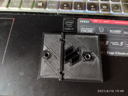
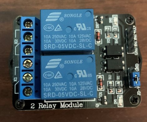
2 Channel Relay DIN Rail Bracket
This is a DIN rail bracket for an 2-channel relay bought from Amazon
May also fit for other 2-channel relays, but I have not tested.
The spacing for the bores is: 33mm x 45mm
Please use the generic PCB DIN Clip and mount this on top.
26 downloads
(0 reviews)0 comments
Submitted
-
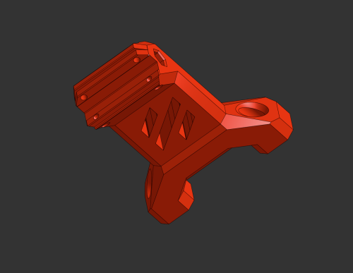
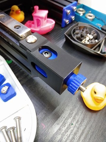
Y-tensioner for the Gizzle Ender 3 Conversion
This mod adds a y-tensioner to the Gizzle Ender 3 conversion.
You will need a base conversion for your Ender 3 in addition to these files. You can find Gizzle's Ender 3 conversion in the VoronUsers github page.
HARDWARE: m5x30 BHCS, m5x16 BHCS, m5x10 BHCS, m5x12 SHCS, m5 Nut (x2 optional), m5 Heatset (optional)
0 downloads
- switchwire
- buzzdalf
- (and 2 more)
(0 reviews)0 comments
Submitted
-
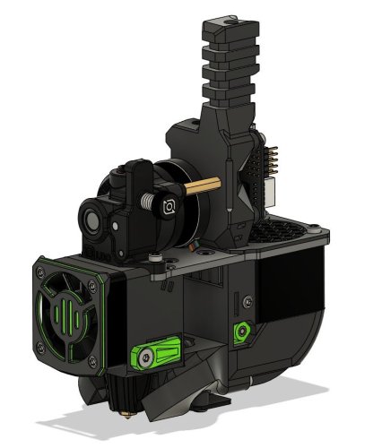
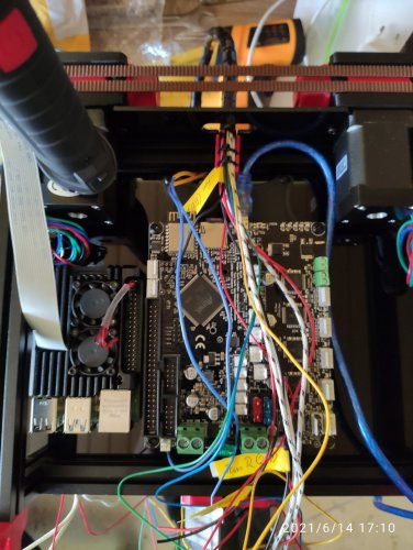
Ender Switchwire Conversion Taller Z
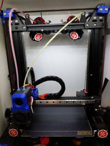
I loved the Ender 3 to Switchwire conversions that Gizzle and Triano did, but I didn't like the idea of losing z-height, so I created this mod. These parts are to extend the usable z-height of the printer back up around 250mm (I get 247mm with it on my own printer). I re-used the upper Z parts Gizzle designed, and am including those here as well so you have everything you need in this repository.
I also designed a bowden guide that will let you route your bowden tube between the belts and the upper cross member of the printer as seen in the picture below. This works really well with a bowden setup, like the dual M4 extruders I use.
You will need a base conversion for your Ender 3 in addition to these files. You can find Gizzle's Ender 3 conversion in the VoronUsers github page.
162 downloads
- switchwire
- ender
- (and 1 more)
(0 reviews)0 comments
Submitted
-
Afterburner Connector Cover
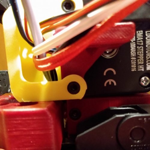
Afterburner connector cover for the LDO 42STH20-1004AS stepper motor for Voron v1.8 and v2.4.
This is a modification of the mod hhammarstrand did for the Switchwire.
That mod does not fit the AB correctly on a 1.8 or a 2.4, so I created a new mod that follows his design principles, but that fit oon a 1.8 and a 2.4
This mod has been verified to fit the LDO-42STH20-1004AS on both a Voron 1.8 and 2.4.
23 downloads
(0 reviews)0 comments
Submitted
-
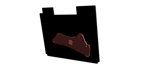
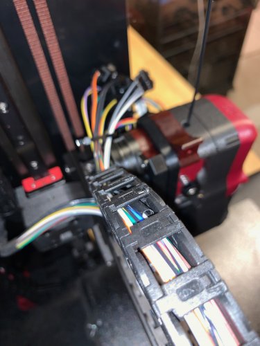
Voron SwitchWire Galileo Chain Mount
The standard chain mount provided for the AfterBurner Clockwork for the SwitchWire does not fit the Galileo Clockwork. This is a modified chain mount to solve that.
The 4 holes that are not a complete pass through are for heated threaded inserts applying.
14 downloads
- switchwire
- btp
- (and 3 more)
(0 reviews)0 comments
Submitted
-
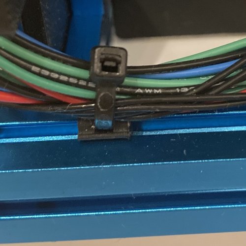
V0 ZipTie Mount
Overview
Some clips for 1515 extrusions to attach ziptie mounts.
Comes in two flavors for LDO and Makerbeam extrusions.
Zipties can be used horizontal and vertical.
32 downloads
(0 reviews)0 comments
Submitted
-
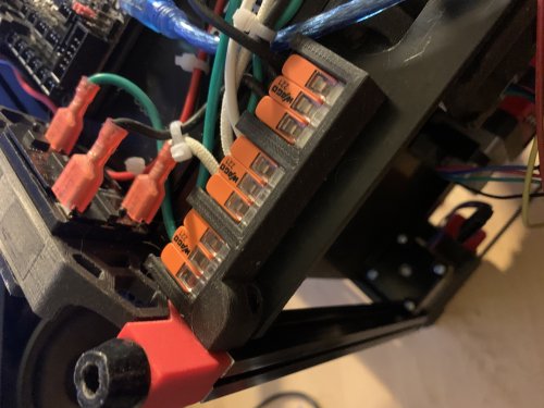
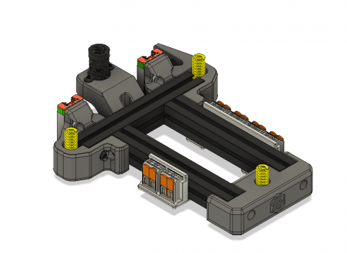
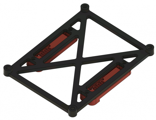
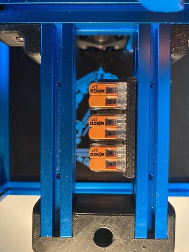
Snap-In Wago Mounts for 1515 extrusions
Overview
This mod is derived from wago_221_mount and brings in some mounts for the Wago 221 terminals (2 and 3 contacts) to clip and to screw for 1515 extrusions.
Wago-Mount for screws
I use this mount WAGO_221-413_3x3-mount-screw.stl at the power inlet to distribute the power to pad/ssr and the PSU. There is also a WAGO_221-412_3x2-mount_screw.stl, if you plan using Wago 221-412 (2 contacts).
Any m3 screw - BHCS or SHCS - should fit.
Snap-In mounts
The snap-in mounts can be easily attached and removed from the extrusions. For using that mount print the desired stl (WAGO_221-412_3x2-mount.stl or WAGO_221-412_5x2-mount.stl together with at least two of the mounting clips(either LDO or MakerBeam depending on your extrusion).
Don't rotate the clips for printing. They must be printed upright, as shown in the picture. Otherwise the clips might break upon inserting into the extrusion.
Use M2 self-tapping screws to attach the clips into the appropriate places of the mount. Screw heads must be flush otherwise the WAGOs won't fit.
Both mounts fit into the Z-Extrusions of the V0
296 downloads
.thumb.jpg.1d984cefa4277697d8fb7de97c93eb2f.jpg)

-
Most Actively Discussed Mods
-
Hottest Files!
.thumb.jpg.2c879d60315f8d86612bb06a137c204a.jpg)