-
TeamFDM.com is an UNOFFICIAL companion site for the DIY Voron 3D printer community. For official docs and final source of truth, visit the Official Voron Discord or the Voron Github
Printable Voron User Mods
Voron User Mods, or "UserMods", are a collection of community created and Team FDM curated modification for Voron Printers. All of these mods are available on the VoronUsers Github repo and unless otherwise specified follow the Voron communities GPL3.0 Licensing. Use any Mods at your own risk, if you make modification please share them on the VoronUsers repo.
Mod Authors: Have a Voron mod? Upload it at TeamFDM.com and let us know you're the author. We will ensure you can update and curate your files for more feedback! Please include tags for what Voron, or extruder your mod is compatible with.
652 files
-

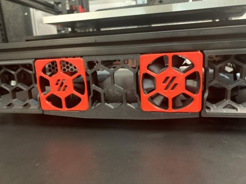
Side Fan Support No Tape
Side Fan Supports with Integrated Fan Mounting
Without deviating from the original design this is what I came up with as an alternative to mounting the side fans with tape.
Instructions for flush front using M2 hardware: Hardware required: 4x M2x16mm screws per fan and 3x M2x6mm per blank insert.
To mount a 60mm fan sandwich the mounting tabs on the side_fan_support between the fan_grill and fan. Note the orientation of the grill, there are recesses for the mounting tabs. Use fan_grill_washer with M2x16mm screws to secure the fan in place. Take care not to overtighten or it will strip. Warning, these do break easily, I'd rather avoid using through bolts instead. If you are gentle, this works. :)
To mount a blank insert sandwich the mounting tabs between the 60mm_fan_grill and fan_grill_retainer using M2x6mm screws.
60mm_fan_emptygrill provided for those who prefer an unobstructed fan.
Instructions for more sturdy install using M3 hardware: Hardware required: 4x M3x25mm screw and 4x M3 hex nuts per fan and 4x M3x6mm screw, 3x M5 washer or 1mm shim, and 4x M3 hex nut per insert.
To mount a 60mm fan sandwich the mounting tabs on the side_fan_support between the 60mm_fan_grill_M3 and fan. Note the orientation of the grill, there are recesses for the mounting tabs. Use either a socket head or button head M3x25mm screw and M3 hex nut to hold in place. Take care that the grill sets into the holes in the fan.
To mount a blank insert sandwich the mounting tabs between the 60mm_fan_grill_M3 and an M5 washer or 1mm shim using either a socket head or button head M3x6mm screw and M3 hex nut. If you use a washer it may be necessary to use two depending on how thick they are.
60mm_fan_emptygrill_M3 provided for those who prefer an unobstructed fan.
Note: For those using the bottom panel a very slight trimming may be necessary around the fan locations. They are shifted over by 1mm so depending on how well your panels fit it may or may not be necessary.
101 downloads
(0 reviews)0 comments
Submitted
-
(0 reviews)
0 comments
Submitted
-
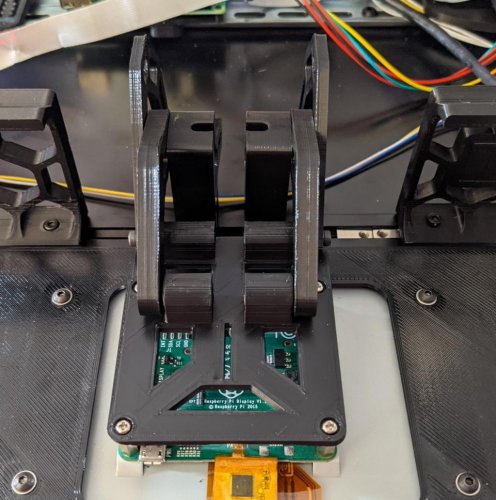
Waveshare 5.5 Inch HDMI AMOLED
Waveshare 5.5inch HDMI AMOLED Mount
This replaces the default Klipper display with a Waveshare 5.5inch HDMI AMOLED display as a skirt to the Voron 2.4.
Required hardware
In addition to things you can reuse from the stock build and to the screw included in the display, these items are required:
4x thread inserts M3x5x4 (same as in the Voron 2.4) 8x M3x8 SHCS82 downloads
-
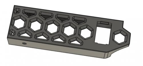
V0 No Drop Nuts
V0 No-Drop Nuts (LDO frames only)
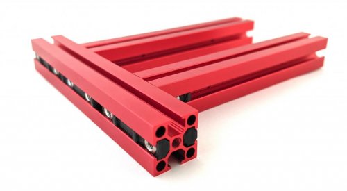
After struggling for hours to build the V0 bed assembly (which requires aligning 4 nuts simultaneously!), I had to do something.
This mod is a whole family of printable inserts to hold your V0 nuts in place, inside the extrusions, and even automatically do the alignment for specific locations.
They fit larger LDO extrusions, but not MakerBeamXL or OpenBeam (yet).
This will make your V0 build go happier, guaranteed, especially for the bed, panel mounts, and mid panel.
Why? They:
hold nuts in place, so you don't need realign, push, or even rotate the printer around automatically align nuts for specific locations on the V0 bed make it easy to align nuts in a row, like for the AB drives, since the 15mm spacing stack matches those No-Drop Nuts in place:
No-Drop nuts in the rear side of the bed:
With these, you can completely assemble a v0 bed assembly in a few minutes.
In general, once you align any nut, you won't have to realign it ever, unless inserting additional nuts.
The 15mm and 12mm versions are generic; use the 12mm for the front idlers on the V0, where the 15mm doesn't quite fit.
Print Instructions
Print Settings: 3 perims, 0.4mm-0.5mm extrusion width, 0% infill, 3 top layers, 5 bottom layers. Align the seam to rear edge. Print as oriented; extrusion-channel-side down. No overhangs past 45 degrees, so should be an easy print.
And you can print these really, really fast. Who's going to see them, anyway?
BTW, you could probably remove most of the material and still have them align and work fine. This didn't seem like a priority, since they each take maybe 90s to print.
Quantities: Quantities are noted for the specific nut locations for a V0. Use 2x of the 12mm for the front idlers. You'll need 24x for the enclosure sides, plus plenty for the skirts, mid panels, rails, and other spots.
Installation
Pop in the nut and slide in. Most parts will align to the extrusion edges or auto-align from a corner.
The sizing is designed to hold them in place, but to make it easy to adjust the position with your fingernail or an allen wrench.
V0.0 Bed-Assembly-specific NoDropNuts
Look carefully, as the picture shows exactly which nuts go where; ones with angled corners fit next to each other on corners. For the V0.0 bed, the filenames correspond to locations, matching this picture.
top left and top right: NoDropNut_Rear_Ext_Rear_Edge_x2.stl top center: NoDropNut_Rear_Ext_Rear_Center_x1.stl left and right middle, with angled corners: NoDropNut_Rear_Ext_Front_x2.stl left and right lower, with angled corners: NoDropNut_Side_Ext_Side_x2.stl NoDropNut_12mm.stl go in the front idlers, and NoDropNut_15mm.stl is your go-anywhere one, to print in sheets.
Design notes
Designed in Fusion 360.
The parts files have 0.1mm of designed-in clearance inside the extrusion in each direection, and they intentionally hold the nut tight, so that the ends bend a bit, to provide a tight slip fit in the extrusion channel.
Credits
Big thanks to grantr for testing an earlier version, called 'SteadyNuts'.
1,959 downloads
-
Z Idler Shoulder Bolt
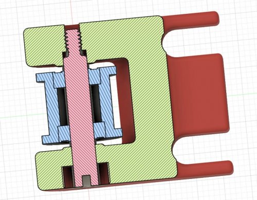
Voron v2.4 Z Idler shoulder bolt modification
Nothing too special, just some small tweaks to the OEM shape to allow for the shoulder bolt. There's a cross-section drawing of the modifications I did, and I used the McMaster-Carr part number: 90265A133 - a 5x20mm shoulder bolt (m4 threaded). You can also purchase them through
8 downloads
(0 reviews)0 comments
Submitted
-
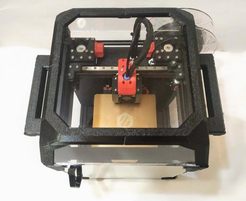
Ender 3Pro Switchwire
Ender 3 Pro and V2 to Switchwire Mod
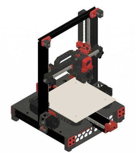
This is a conversion of the Ender 3 Pro and V2 to a Switchwire type coreXZ printer. My goal was to use most of the Ender 3 components while maintaining the core Voron design look and feel.
Overview
This mod uses most of the key components from the Ender 3 Pro (E3P) while providing a coreXZ capability. The highlights of this include: The frame is all E3P. The electronics are the stock Switchwire ones, but the E3P 24V power supply is used. I wanted to get all the electronics under the deck as this follows the Switchwire design. I had to get a little creative with the mounts to make this work. I did not include the LCD display. Mainsail (MainsailOS) is so amazing, I never use the LCD on the Voron 2.4 so I left it out. It can easily be added. The deck is easily printed in 4 sections. The XZ and gantry are slightly modified from the Switchwire baseline. The X axis rail is 300mm and is a tight squeeze on the shortened 2020 extrusion. I wanted to keep the standard rail length in case I wanted to build a stock Switchwire. The Y axis uses 2 rails. I liked the look of it and it seemed more stable that way. It also simplified the Y belt routing through the extrusion. I also removed the springs on the bed corners and replaced them with spacers. The spacers come off the E3P V-wheels. With the bed mesh probing, this seemed like a better approach than worrying about the bed changing positions if the knobs rotated/loosened. This configuration also worked without too much modification to the stock E3P wire lengths. The E3P motors can be reused if you can pull off the gears. Thingiverse has a printable gear puller (I haven't tried it). Images / CAD
I have included several images and the Fusion 360 CAD model. CAD files and images are included in the repository
BOM
A BOM has been added that is based on the baseline Switchwire. This will not be perfect as the Ender 3's get a lot of mods by their owners. It should help with most of the key items to make the MOD.
Firmware:
Use the baseline Switchwire configuration available in the Voron-Switchire repository. The Voron-documentation has excellent instructions for making the adjustments.
STL Files
This mod uses a combination of original Switchwire and modified parts. Most of the parts are modified/new as the Switchwire and Ender 3 frames are much different. I kept all the Voron naming conventions to provide consistency. The following is a listing of the STL files, organized by location:
Deck:
[a]_deck_y_chain_anchor deck_front_right deck_front_left deck_rear_right deck_rear_left Electronics:
[a]_ps_clamp [a]_ps_hanger [a]_rpi3_mount [a]_rpi3_shelf [a]_rs_25_hanger [a]_skr_mini_e3_mount 2020_ziptie_clip (quantity as required to suit your wiring organization) Grill:
[a]_grill_endcap_x4 grill_front_left grill_front_right grill_rear_left grill_rear_right XZ-Axis:
[a]_xz_cable_cover keybak_mount_plate_a keybak_mount_plate_b x_motor_mount_a x_motor_mount_b xz_block_left_a xz_block_left_b xz_block_right_a xz_block_right_b z_bearing_block_left z_bearing_block_right_generic z_carriage_stop_x2 z_motor_mount_a z_motor_mount_b [a]_xz_tensioner_x2 ** [a]_upper_idler_support_b_right ** [a]_upper_idler_support_b_left ** upper_idler_support_a_right ** upper_idler_support_a_left ** keybak_gantry_anchor ** keybak_idler_bracket ** Y-Axis:
[a]_y_axis_anchor_x2 [a]_y_axis_frame_chain_anchor [a]_y_axis_ls_mount [a]_y_front_belt_mount [a]_y_front_belt_slider [a]_y_motor_mount_a [a]_y_motor_mount_b y_axis_bed_carriage Misc:
2020_MGN12_guide_x2.stl ** 4040_rail_tool ** Denotes STL files that have not been modified from the baseline Switchwire design and are located in the Switchwire repository
2,053 downloads
- triano
- switchwire
- (and 2 more)
-
4inch Touchscreen Mount For V2.4
4-inch Touchscreen for OctoDash - Voron 2.4
OctoDash
OctoDash is a very cool dashboard / touchscreen UI for OctoPrint that you can download and install on your Raspberry Pi. It is recommended to configure your Pi with auto-login to desktop and auto-launch the OctoDash app at startup.
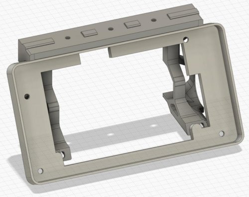
Touchscreen and Cables
Octodash will work with almost any display attached to the Pi but I found this really nice 4-inch IPS touchscreen on AliExpress that is perfectly suited - so I built a mount to integrate it into the V2.4 skirt as a drop-in replacement for the stock front panel. As such it should work on any size V2.4 (250/300/350) with the stock left- and right- front skirt pieces.
When buying this screen I recommend you choose the
58 downloads
(0 reviews)0 comments
Submitted
-
FilteredPower
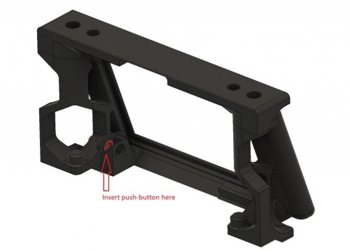
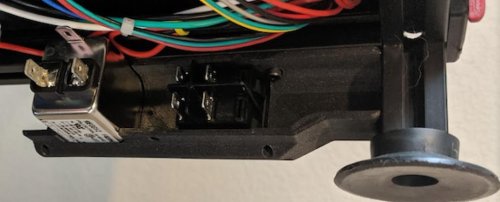
Filtered Power for Voron 1.8
This mod allows the use of the prior spec TycoElectronics filtered power inlet and ZF rocker switch. The skirt can be configured to a custom X-Spec as needed (assuming you modify the other skirts) using parameters in Fusion 360.
Pictures
A special thanks to Venny#8759 on discord for testing and providing the pictures!
2 downloads
(0 reviews)0 comments
Submitted
-
Micro Backplate
Scrolling through Discord, there are V0 owners like me that experienced really hot electronics or motors because of the enclosed back of the printer. As a serious adult without kids or furry kids, you could leave the backplate off the printer to allow for airflow for the electronics/motors. Unfortunately this will result in losing hot air from the print chamber. So in addition to Weaslus
2 downloads
(0 reviews)0 comments
Submitted
-
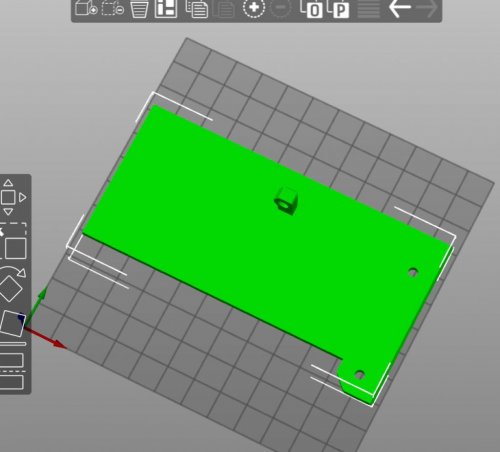
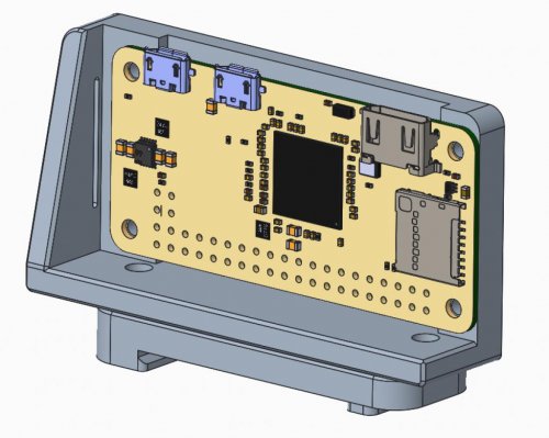
Rbp Zero Braket
This is a bracket for a raspberry pi zero / w the bracket mounts to the din rail using
5 downloads
(0 reviews)0 comments
Submitted
-
Skirt Switch Mod
V2.4 Front and Side skirt with switch mod
Follow the manual for instructions on installation and wiring.
NOTE: I am by no means a CAD professional. I have only tested the 300mm mods. Feel free to contact me on the Voron discord (tayto-chip) if you would like the step files.
All screw and heat-set insert holes are unchanged.
Switch used is from the V2.4 sourcing guide: ZF Rocker Switch
Images
147 downloads
-
-
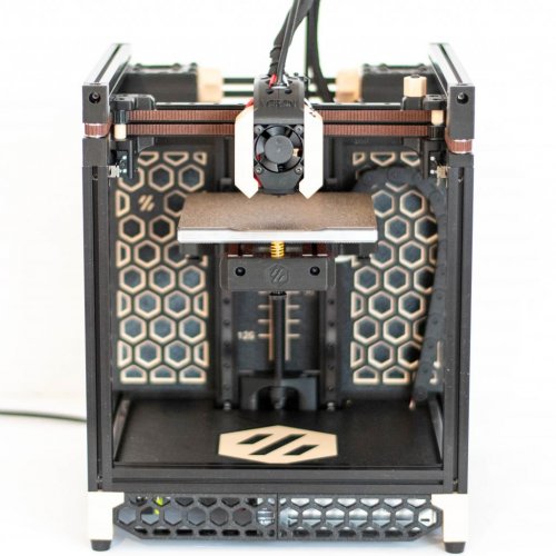
GhettoPanels
A Team Dropbear Production
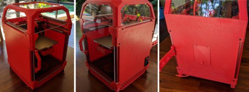
Voron Zero Printed Panels
G'day, Dr Ghetto here coming to you with money saving tips from down under. Too tight to buy acryllic? Too lazy to cut, saw or otherwise manually fabricate panels for your cute little Voron 0? Well you're in luck. This mod is a set of printed panels, ghetto panels if you will. Buckle up bozos, deets to follow.
The right hand panel integrates the front door hinge mount. You don't need to print any corner pieces at all. A side panel is 248 x 237mm so maybe you can print it on a 250. Do you feel lucky punk? The panels mount with two holes a side, so be sure to drop a nut from stock.
Word in the hood is you guys like it from the rear, so the back panel has a hatch to access the extruder. The stock spool holder fits with the back panel. If you printed the beta deck-panel-rear.stl then it blocks the ptfe tube. The Doctor shivved that sheet until it fit, because that's how we roll in the ghetto. Get yerself some hot foot-filament-guide.stl for a modded rear foot which grasps that sweet tube like Mrs Ghetto, know what I'm sayin'.
Printing and plasic
Good to go with 0.6mm nozzle, 0.3 layer height. The panels print outside down. This works real nice on textured surfaces. If you're using a smooth surface, maybe you wanna use a nice top pattern, or no bottom layers for dat exposed infill look. Yeah baby.
Plastic? The ghetto abides. Always gonna be that guy that prints it in PEEK but anything you can print without major warp is ghetto approved. After that, it's a bling thing. Show us what ya got!
Alt parts
The mount holes are slotted to deal with ABS shrink but but shrink is bad for hinge alignment. Like duct tape on your AK, the ghetto has your back with remixes of the front right panel hinges panel_hinge_bottom.stl and panel_hinge_top.stl designed to fit standard ABS shrink.
The right hand panel has two versions, panel_right_iec.stl has a cut-out for the commonly available* switched and fused IEC power inlet, part number JR-101-1FRS. These are like eight bucks down under and they're officially ghetto approved. This part is for a 1mm (metal) panel so some silicone sealant is advised. As the hacker sage Naomi Wu once said, you can never have too much silicone.
-DrGhetto (Calozor#1514)
* In Australia. Hahahaaa `` You have no idea how much I've wanted to say that.
33 downloads
(0 reviews)0 comments
Submitted
-
V1.8. Z Rails Mod
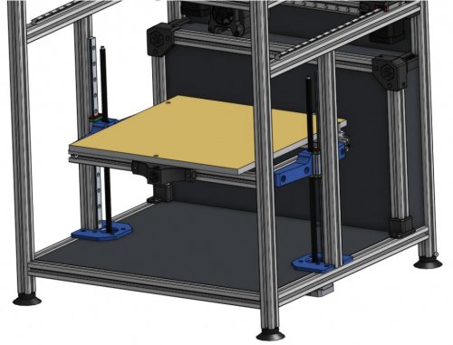
V1.8_Z_Rails_Mod
Z Linear Rail Mod for Voron 1.8 (300x300x250)
Parts list:
2 modified z motor mounts (printed in abs with the standard voron settings) 2 leadscrew-mgn12 blocks (printed in abs with the standard voron settings) 2 mgn12h (300mm long for 250 z) 4 m3x16 shcs (fasten lead screw nut to block) 4 m3 nuts (fasten lead screw nut to block) 12 m5x16 bhcs (fasten blocks to extrusions and extrusions to frame) 8 m5 t-nuts 8 m3x20 shcs (fasten blocks to mgn12's) 2 Misumi HFS5-2020-340-TPW (vertical extrusions for 250 z height) 12 m3x8 shcs (fasten mgn12 to extrusion) 12 m3 t-nuts 2 Misumi HFS5-2020-350-AH10-BH340 (x extrusions for 300x300 bed frame)
Notes:
The z motors are shifted inwards 2.07 mm (towards the center of the bed) so you must modify the deck panel slighly. This was necessary to provide clearance for the rails. See the dxf folder for the modified dimensions.
The y extrusions have an allen key clearance hole drilled 170.8 mm from the front end cut. This is for the blind joint that fastens the new extrusions the mgn12's are mounted to. These 2 extrusions are in line with center of the bed. It is very important that the end cuts are square and exactly the same length. This can potential bend your gantry extrusions if they are not square. I did not have any issues with Misumi's end cuts. Others have used right angle brackets with success and this might be a better way.
I've added leadscrew-mgn12 block stl's for both the 300 and 250 build sizes so choose accordingly. I had trouble with warping when printing the leadscrew-mgn12 blocks on my ender 3 with a glass bed. Elmers purple gluestick on the buildplate saved the day. These blocks have been tested with the link cnc 8x2 and bigtreetech 8x8 integrated lead screws. I highly recommend the bigtreetech 8x8 lead screws with the only downside being that the bed drops slighly when the motors turn off.
You can center the mgn12 to 2020 extrusions using the stl located in the switchwire repo here.
The 2 bed extrusions in the x direction are shortened to 350mm because they're no longer necessary to hold the lm8luu bearing mounts. Although the stock length extrusions (420mm) will still work, they will be protruding out in space.
Let me know if you have any questions or need anything. There is also a video of my mod on youtube if you would like to see it in action.
33 downloads
(0 reviews)0 comments
Submitted
-
Mini12864 LCD Mount For V2.4
Swiveling case for the Fysetc Mini12864 LCD
Overview
This is a Fysetc Mini12864 LCD case for the Voron 2.4, inspired by Schlank's Minima case. The design integrates the aesthetics of the Minima, while it preserves the ability to swivel from underneath the frame extrusion.
BOM
1x Fysetc Mini12864 Display 4x M3x8 SHCS. 4x M3x12 SHCS. 6x M3 Heat set inserts (M3x5x4). 2x M3 T-nut HNTAJ5-3. Super-glue or similar. Printing instructions
The parts are easy to print, designed around 0.4mm line width, 0.2mm layer height and no need for supports. Print the base and rear cover in your main color and the display cover and hinge in your accent color. The design is compatible with the Voron 2.4 skirts. Pro tip: use variable/adaptive layer height to print the rounding edges of the base with a lower layer height.
Assembly instructions
Pre-assembly, please note that the Fysetc Mini12864 Display has reversed EXP1/EXP2 connectors. If you use this display in combination with a SKR controller board, please reverse these connectors by carefully pulling the connector housing from the display board and re-install them over the bare pins, turned 180 degrees.
Test fit the LCD display with the base, display cover, hinge and rear cover. Glue the display cover to the base with super-glue or similar. Press all 6 heat set inserts in the base with a soldering iron. Mount the hinge to the base with 2x M3x8 SHCS bolts. Control the swiveling tension with these bolts. Bolt the Mini12864 display board and the rear cover to the base with 4x M3x12 SHCS bolts. Press the potentiometer knob in place. Install case to the extrusion with the remaining 2x M3x8 SHCS bolts and 2x M3 T-nut HNTAJ5-3. Klipper configuration
The example below is provided for SKR1.3 boards with the display cables connected to the Z MCU.
[display] lcd_type: uc1701 cs_pin: z:P1.18 a0_pin: z:P1.19 encoder_pins: ^z:P3.25,^z:P3.26 click_pin: ^!z:P0.28 contrast: 63 Following section should be added to control the LCD backlight:
[neopixel my_neopixel] pin: z:P1.21 chain_count: 3 initial_RED: 0.0 initial_GREEN: 0.0 initial_BLUE: 1.0 color_order_GRB: False It is possible to include code in your print macros to change the color of the LCD backlight for different printing stages (pre-heat / printing / finish / etc.)
Please refer to klipper documentation for further info.
Early contributors / testers
Daniel H. StvPtrsn Navy_Chief Knuckl3dragg3r Questions
Hit me up in Voron's Discord if you have any questions.
121 downloads
(0 reviews)0 comments
Submitted
-
V0 Skirt Mod
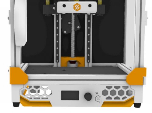
V0 Skirt mod One piece, dual color, built in V0 Display and C14 in the rear
53 downloads
(0 reviews)0 comments
Submitted
-
Ender 3 To SW
My edited DXFs to work with my modded Enderwire. Too lazy to poke holes, so mine didn't have any
491 downloads
(0 reviews)0 comments
Submitted
-
(0 reviews)
0 comments
Submitted
-
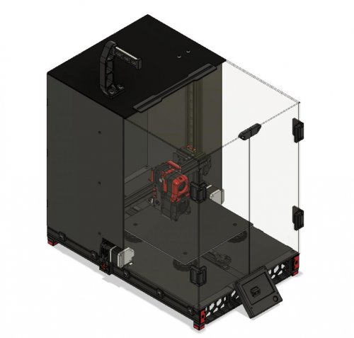
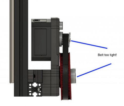
V0.1 Belted Z Drive
Same BOM as the original mod for the V0.0
BOM located at:
https://docs.google.com/spreadsheets/d/1Ucntdw1GGza19FC4mE_vLksJp4SiwUsq-mJtIgG-_OQ/edit?usp=sharing
NOTE: This is a beta release. Still testing and some minor design changes may occur in the future.
1 download
(0 reviews)0 comments
Submitted
-
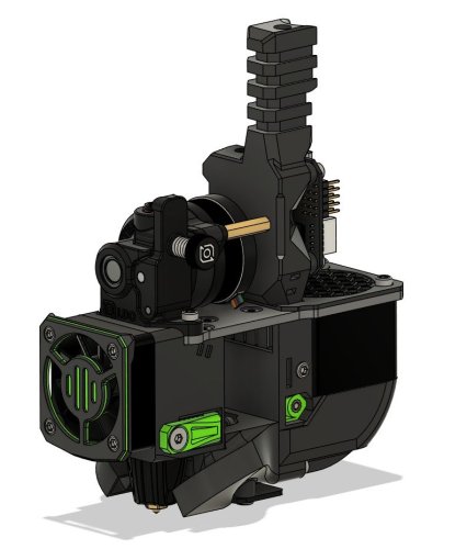
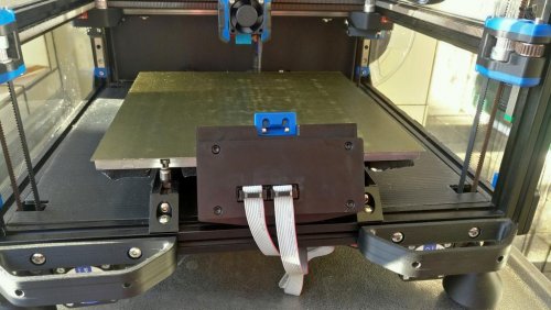
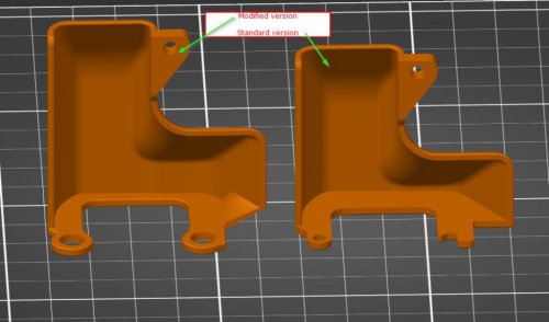
Afterburner Connector Cover 42STH20 1004AS
Afterburner connector cover for 42STH20-1004AS stepper motor
The Afterburner is designed for the 17HS08-1004S stepper motor. This stepper has notches where the motor body is screwed together and the connector cover uses the space inbetween the cable chain connector and the notch. My Afterburner uses an LDO-42STH20-1004AS2 which doesn't have this notch, hence this modified cable cover. This cable cover is designed to not need any new hardware and therefore is attached on top of the screw heads instead of being held down by the screws. This also makes the removal of the cover a little quicker, since you only have to unscrew 1/3 of the screws. There is also a little more room for cables since the cover is longer and the exit hole is a little larger.
Verified to fit on
LDO-42STH20-1004AS2 on SwitchWire Comparison to the original connector cover
What is modified from the original?
A few mm longer so that it goes past both the motor and the cable chain mount Larger cable exit so that my wires fit better A little bit modified in the back not to hit the cable chain Larger holes for the screws since this is actually not bolted down, it just snaps in place on top of the bolt heads BOM
Just this printed part, everything else is stock User photos
User Exodius Afterburner with this mod installed
47 downloads
(0 reviews)0 comments
Submitted
-
V0 Handle
Voron0 Handle for 3mm panels
print settings:
layer height: 0.2mm hardware:
8 x M3x35 SHCS 8 x M3 nut
18 downloads
(0 reviews)0 comments
Submitted
-
V0 Skirt
Voron0 dual color skirt set (SSR, PowerSwitch, Nameplate)
To match the skirt with the Midpanel with Hex Pattern by sterminatore's idea
print settings:
layer height: 0.2mm color change at 0.6mm / 2.2mm Skirt.stl, Skirt_mirror.stl
Left and right skirt part with 40 degree chamfers for color change printing. There is an extra hole for tightening the middle M3 screw.
Skirt_EmptyNameplate.stl
Empty nameplate for serial number. For example, with Tinkercad you can easily put the number on it.
Here's a quick tutorial:
Skirt_SSR.stl
SSR holder with led window.
Skirt_PowerSwitch.stl
12mm x 19mm windows for power switch.
Example power switch on aliexpress: On/Off Switch 6A-10A 110V 250V 21MM*15MM
Overview
36 downloads
(0 reviews)0 comments
Submitted
-
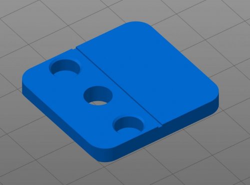
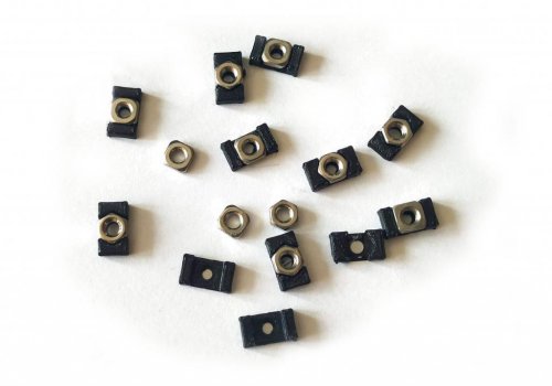
V0 1515 T Nut
Voron0 1515 T-Nut
It is a great help during installation to prevent the nuts from moving. During the construction of Voron0, it comes in very handy with the screws of MidPanel, TopHat, BedMount.
hardware:
M3 Square Nuts from Aliexpress (5.5mm x 5.5mm x 2mm) (Recommended!) or
M3 hex nuts. The hex nut is too high, it is difficult to print because only one or two layers get under the nut. (depending on the frame) But it also works. The MakerBeam version is lower than the LDO version.
print settings:
layer height: 0.2mm
134 downloads
-
V0 MidPanel HexPattern
Voron0 MidPanel with Hex pattern
print settings:
layer height: 0.2mm color change at 0.6mm / 2.2mm V0.1
hardware:
4 x M3x8 BHCS 4 x M3 nut
V0.0:
Compatibility:
Pocketwatch Z Belt mod hardware:
8 x M3x6 BHCS 8 x M3 Threaded Insert 4 x M3x8 BHCS 4 x M3 nut
264 downloads
(2 reviews)0 comments
Submitted
-
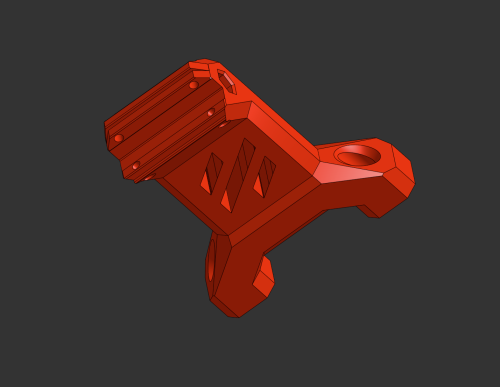
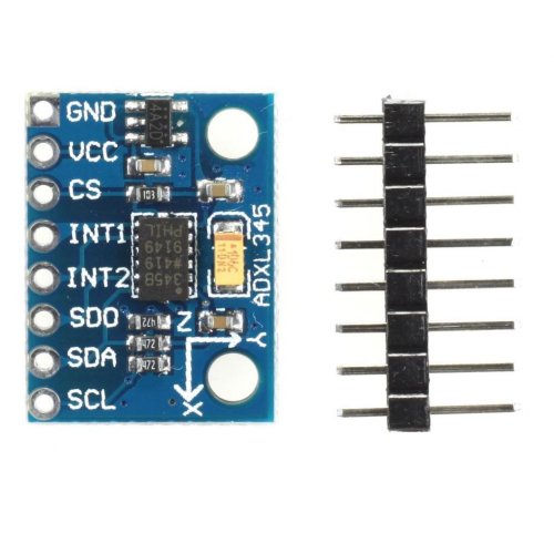
GalileoADXL
ADXL356 mounts for the Galileo extruder
These are my edited standard galileo chain mounts to be able to mount an adxl356 against it permanently. I attached them with two M3x6. It'll work for an adxl356 of the following layout: It'll end up looking like this:
13 downloads
(0 reviews)0 comments
Submitted
-
Most Actively Discussed Mods
-
Hottest Files!
.thumb.jpg.2c879d60315f8d86612bb06a137c204a.jpg)