-
TeamFDM.com is an UNOFFICIAL companion site for the DIY Voron 3D printer community. For official docs and final source of truth, visit the Official Voron Discord or the Voron Github
Printable Voron User Mods
Voron User Mods, or "UserMods", are a collection of community created and Team FDM curated modification for Voron Printers. All of these mods are available on the VoronUsers Github repo and unless otherwise specified follow the Voron communities GPL3.0 Licensing. Use any Mods at your own risk, if you make modification please share them on the VoronUsers repo.
Mod Authors: Have a Voron mod? Upload it at TeamFDM.com and let us know you're the author. We will ensure you can update and curate your files for more feedback! Please include tags for what Voron, or extruder your mod is compatible with.
652 files
-

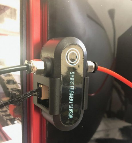
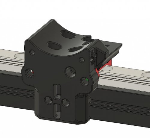
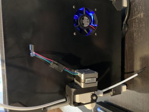
BTT Filament Motion Sensor Mount
BTT Smart Filament Motion Sensor mounts
Overview
I always liked the motion sensor on my original Prusa MK3 and was very disappointed when they switched to a mechanical solution that cannot detect motion on the MK3S. So I was pleased to see that Big Tree Tech picked up the idea and even improved the reliability. The MK3 had an optical sensor that tried to detect the filament itself which caused some issues with some type/colour of filament. In the BTT sensor the filament drives a wheel that is then detected by an optical sensor. I did not want to add more weight to my x-carriage, so I designed the mount for the extrusion profiles, outside the printer housing.
Description
These mounts fit for the BTT Smart Filament Motion Sensor. You can also use two of the housing screws and I have seen other mounts that replace the back of the housing, but I wanted something that is easy to remove, if I have to. You just have to unplug the cable and then the sensor snaps into the mount. To unmount unplug the cable first. I have created two versions to mount the part vertically or horizontally.
The installation with BTT SKR boards is easy. The connector already fits to the board connector like the E0 DET.
S=Signal, G=Ground(-) and V=Voltage( 3.3-5V)
The next step is to configure Klipper. If you use the E0 DET connector then the pin is P1.26 (or xP1.26 if you connected to the x board). It is documented here -
211 downloads
(0 reviews)0 comments
Submitted
-
Terminal Blocks NC933 SPL 62
Mounts for Power Terminals from AliExpress
Overview
I found those no-name power terminals on AliExpress and found them useful to distribute the power in the Voron. So I designed a mixup from the PSU DIN rail mounts for them. !! Use them at your own risk like any other electrical part in your printer. !!
Description
These mounts fit for the SPL-62 and NC-933 1to3 power terminals that can be found at Electrician Electrical Store on AliExpress. I do like the compact design over the WAGO or Phoenix Contact terminals. They do have a strong clamping force, but I would not trust in the sellers specifications of 32 Amps. For the use in a Voron they should be fine.
NC-933 (https://de.aliexpress.com/item/4001236902340.html) SPL-62 (https://de.aliexpress.com/item/4000505115328.html)
You can use two M2 self tapping screws to mount them I recommend a stack of washers or a 3D printed spacer for the SPL-62 as the mount holes are not flat on the backside. Again, use them at your own risk. You should not work on mains voltage if you don't know what you're doing. And your printer should be properly protected by fuses, circuit breakers or even a ground fault circuit interrupter. If you have any concerns, don't use them, get genuine WAGO/Phoenix Contact instead!
7 downloads
(0 reviews)0 comments
Submitted
-
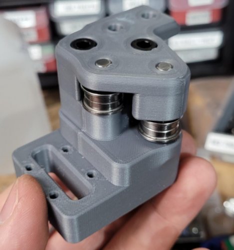
Voron2.4 Pins Mod
This mod is for the V2, it involves printing new AB drive frames, new XY Joints, new Front Tensioners, and new Z idlers
The pins have replaced m5 screws, at any location where the screw acts like a shaft, holding bearings, pulleys or idlers. This allows for smoother rotation and stops the possibility of motion parts being caught in threads. This work was done by everyone, thanks to ABS plastic and voron printers for the fast iteration, @doomweasel? they fall out yet?
To complete this mod the following files will need to be reprinted
A and B drive units
a_drive_frame_lower_pinned.stl a_drive_frame_upper_pinned.stl b_drive_frame_lower_pinned.stl b_drive_frame_upper_pinned.stl Front Idlers
[a]_a_tensioner_pinned.stl [a]_b_tensioner_pinned.stl XY Joints
NOTE: There are now 2 versions of these files , 1 set for Stock 2.4 and 1 set for Arkeets MGN12
xy_joint_left_upper_pinned.stl
xy_joint_left_lower_pinned.stl
xy_joint_right_upper_pinned.stl
xy_joint_right_lower_pinned.stl
or
MGN12_xy_joint_left_upper_pinned.stl
MGN12_xy_joint_left_lower_pinned.stl
MGN12_xy_joint_right_upper_pinned.stl
MGN12_xy_joint_right_lower_pinned.stl
Z Idlers either one of these based on if you are using 6mm or 9mm belt
[a]_z_tensioner_x4_6mm_pinned.stl [a]_z_tensioner_x4_9mm_pinned.stl here is what the XY Joint will look like
There is a new file for the A Drive to go along with Arkeets MGN12 mod that has the X endstop on the toolhead
the files for the endstop relocation mod are here Voron2.4_Y_Endstop_Relocation
the following 5mm Pin hardware is what is needed as well
BOM
[A-B] threaded @ 30mm (x2) smooth @ 28mm (x2) [X-Y Joints] smooth @ 40mm (x4) [X-Y Idlers] smooth @ 43mm (x2) [Z Idlers] smooth @ 28mm (x4) these can be purchased from here
Smooth pins
https://www.aliexpress.com/item/1739093502.html
threaded pins
https://www.ebay.com/itm/φ5mm-φ12mm-Female-Thread-Cylindrical-Pin-Dowel-Pins-A2-304-Stainless-Steel/184373551069
Misumi Part Numbers
Part NO. Qty SFRT5-30-M3 2 SFR5-43 2 SFR5-40 4 SFR5-28 6 NOTE: 2 smooth pins can be substituted for the threaded pins, the reason the threaded pins are there is for easy removal without the need to remove the stepper. but if you dont plan on removing the pins without removing the stepper than smooth pins would work just fine for you in this situation.
The following users are the main contributors to this mod
@RoboDave
@DeepFriedHeroin
@Hartk
@DOOMweasel
@Eddie
5,048 downloads
(0 reviews)0 comments
Submitted
-
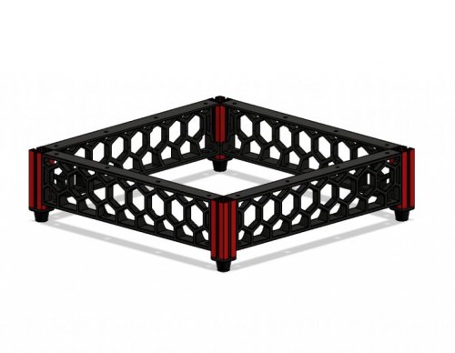
Voron0 ExtrusionSkirt
Extrusion Skirt and Legs
This is a new skirt system that uses 50mm extrusions for legs and has a power inlet in the rear skirt
Misumi Part # for the new legs is HFS3-1515-50
Pictures
9 downloads
(0 reviews)0 comments
Submitted
-
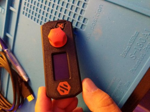
Voron0 Display Dualcolor
Dual color for the V0 Display housing
i modified the file to make it so the logo can be printed in an accent color as well as the stop button
15 downloads
(0 reviews)0 comments
Submitted
-
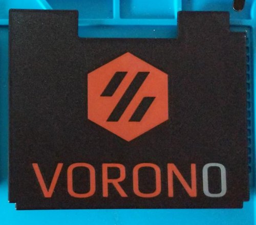
Voron0 Deck Panel With Logo And VORON0
Deck Panel for V0 to include the Voron logo and the VORON0 name
i used user @Kruppes blank deck panel to make my own to include the logo as well as the words it uses 3 colors hence the 2nd accent label on the 3rd stl [b], i used black for the base, red for the logo and gray for the
54 downloads
(0 reviews)0 comments
Submitted
-
Voron0 MGN9C X Axis
MGN9C X axis
This replaces the MGN7H rail on the V0.1 X axis with a single MGN9C rail.
Required hardware
In addition to things you can reuse from the stock build, these items are required:
1x MGN9C-150mm linear rail 7x M3x8 7x M3 Nuts Instructions
Assembly is exactly the same as the stock V0.1 X axis
Images
282 downloads
-
Voron0 Hinged Top Hat
Hinged Hat for the V0
This is my new design for a fold away hinged top hat for the V0, i have included the step file for all the parts i designed, as well as added a BOM for everything you need to get in order to build this,
assembling is pretty straight forward i have added the steps i took when assembling it in picture form here
Step 1
NOTE: This step uses M3x12 screws
Is to attach the bottom hinge pieces to the top of the V0 first with the little pegs on the bottom of the bottom hinges going into the holes on the A and B drive parts on top of the V0 using M3x12 screws
Step 2
NOTE: This step uses M3x16 screws
attach the 200mm extrsusion to the printed parts
Step 3
NOTE: This step uses M3x8 screws
next is the rear frame for the top hinge assembly, attach the two top hinge pieces to a 200mm extrusion as shown, be aware that these pieces are mirrors of eachother and it matters which side they go on, they are attached using m3x8 screws
Step 4
NOTE: This step uses M3x8 screws
next is to add these 200mm extrusions to the top hinge assembly created in previous step, these also use m3x8 screws
Step 5
NOTE: This step uses M3x8 screws
attach the 2 80mm extrusions up against the top hinge assembly
Step 6
NOTE: This step uses M3x8 screws
attach the 170mm extrusions that go up against the 80mm extrusions
Step 7
NOTE: This step uses M3x8 screws
now add the 92mm extrusions to the front of the frame, now these are 92mm long but the gap between the top and bottom extrusion is 95mm, you want the top of the extrusion to be flush and leave a little gap in the bottom of them which is for the alignment pins
Step 8
NOTE: This step uses M3x8 screws
these are the alignment pins, they are used to register in the holes on top of the front idlers on the V0 and they just attach to the bottom of the 92mm extrusions
Step 9
NOTE: This step uses M3x8 screws
attach the 2 front extrusion and you should have the completed frame now
Step 10
NOTE: This step uses M3x20 screws
what I would do next is attach the bottom hinge and top hinge together using the middle hinge assembly you made in step 2 and check to make sure every thing is moving correctly and lining up properly, and make any adjustments you see fit.
final step
Once the frame is moving correctly and everything is working well together, add the panels to the top hat to enclose it completely there are 2 panels that go in the back the inner one can be left out, I originally didn't have the final rear printed panel but now that it's there , the inner rear panel is no longer needed
Screw size and locations
bottom hinge uses m3x12 to attach to the frame using an m3 nut that needs to be slid into the top extrusion of the V0, I did this by unscrewing the front of it from the idler bracket and just dropping a nut in the extrusion
top hinge which also uses an m3x12 and m3 nut in 1 of the 3 holes to attach it to the bottom of the top extrusion of the hat frame the other 2 are m3x8 and are screwed into the ends of the extrusions
the middle hinge (middle screw) is an m3x16 and it screws into the end of the middle extrusion
the middle hinge (2 outer screws are m3x20) they screw into embedded nuts on the back of the middle hinge piece
i hope the pictures help with assembly they are named in the correct order to assemble it
when it comes to drilling the holes in the extrusions to screw them together, there is a drilling guide stl in the stl folder and it has 3 holes, the one closest to the end is for the 92mm extrusions on the bottom of them, the same end that the alignment pin stl gets screws on. the middle hole in the driling guide is just a standard 7.5mm from the edge to make normal blind joints you did with the v0 and the highest hole is to attach the 80mm extrusion to the top 200mm extrusion (you drill the hole in 200mm extrusion)
i found it easier to assemble it from the back of the top hat forward. if you open the step file you can see how it assembles. i have tested this quite a bit and so far its been working great! please feel free to make any modifications to it as you see fit
i hope you enjoy it
-hartk1213 V0.108
BOM
1515 Extrusions
Length (mm) Qty Misumi Part Number 200 5 HFS3-1515-200 170 2 HFS3-1515-170 92 2 HFS3-1515-92 80 2 HFS3-1515-80 Enclosure Panels
Location Dimensions Qty Front 212x76 1 Sides 182x76 2 Top 212x212 1 Rear 212x59 1 Screws
Size Qty M3x8 68 M3x12 4 M3x16 2 M3x20 4 M3 Nuts 64 Pictures
120 downloads
-
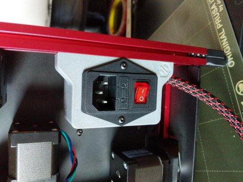
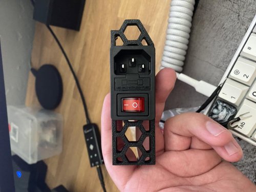
Voron0 C14Inlet
C14 Fused inlet for the V0 with a cover on the back to cover the contacts
This is a mount for a c14 fused inlet found here on amazon https://smile.amazon.com/Antrader-Module-Socket-Switch-IEC320/dp/B07CTC5JVV
this uses 2 M3x40 screws to assemble and 2 M3x12 screws to attach to the frame
Pictures
5 downloads
(0 reviews)0 comments
Submitted
-
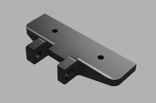
Voron2.4 Y Endstop Relocation
This mod moves the Y endstop to the A drive, to go along with Arkeet's MGN12 mod that has the X endstop on the toolhead. This mod requires a 2 pin JST-XH to be soldered to the switch. The best way I have done it is to solder the wires to the JST-XH first, install it with a dab of super glue, then solder the wires to the Omron switch.
There are 2 different files
non pinned version
a_drive_frame_upper_with_jst_y_endstop.stl pinned version (since this mod also works with the Voron2.4_Pins_Mod):
a_drive_frame_upper_with_jst_y_endstop_pinned.stl here are a few pics for reference
you might need to bend the pins a little bit to get them to fit around the curve
256 downloads
-
60mm Shaft Jig
Simple jig to cut Z drive shafts to length and grind flats along one edge.
10 downloads
(0 reviews)0 comments
Submitted
-
V0 Mods
Simple LED mounts to run along the top of the V0 frame.
12mm mounts are sized for a 12mm wide LED strip. This was used for a small strip of RGBW LEDs. 10mm mounts are sized for neo pixels strands. One has a channel so that the data pin can be routed to the other side.
18 downloads
(0 reviews)0 comments
Submitted
-
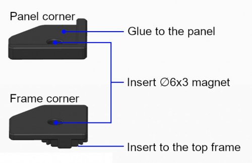
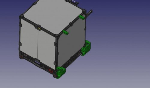
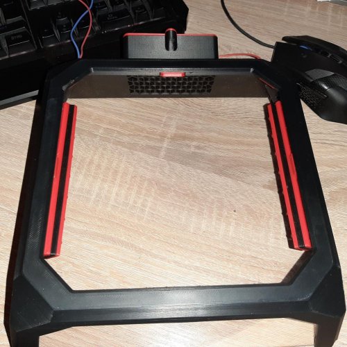
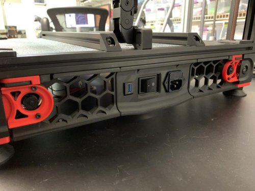
Magnetic Top Panel
Magnetic top panel
Overview
This top panel can be easily removed for printer maintenance or giving more cooling. 3D models are designed to match your buildplate size. For versions 1.8 and 2.4 in 250, 300 and 350mm.
https://user-images.githubusercontent.com/85416803/124365758-a2454180-dc0f-11eb-9ac9-38a180425a46.mp4
BOM
250:
400 x 400 x 3mm acrylic panel sheet
4x 344mm of 6 x 11,7mm [1/2” x 1/4”] High density foam
300:
450 x 450 x 3mm acrylic panel sheet
4x 394mm of 6 x 11,7mm [1/2” x 1/4”] High density foam
350:
500 x 500 x 3mm acrylic panel sheet
4x 444mm of 6 x 11,7mm [1/2” x 1/4”] High density foam
Core:
8x Ø6 x 3mm neodymium magnet
Acrylic sheet with abrasion resistant coating may be considered for V1.8 to prevent micro scratch caused by the reverse bowden tube. This may also appear with full height prints on V2.4. I don’t recommend using glass plate because of its weight, this may result in broken top skirt and broken glass!
Instructions
Insert magnets into panel corner and frame corner respecting their polarity. Insert frame corner on top of the 4 vertical 2020 extrusions. Put panel corner on frame corner, sides should be flush. Glue* the acrylic panel sheet on panel corners, be sure to keep panel corner and frame corner sides flush while gluing the acrylic panel. Remove the panel from the frame, adjust foam length and glue it under the acrylic panel sheet (same side as panel corner). Glue* top corner skirt on the acrylic panel sheet. Adjust top skirt length and glue* on the acrylic panel sheet. You can easily adjust the length in your slicer. * Any liquid super glue works fine, be sure to not use VHB tape as you will add an extra height that will cancel the foam seal. # # #
54 downloads
(0 reviews)0 comments
Submitted
-
V0 Dragon ToolheadStockScrews
Modded Dragon Toolhead
This is a small mod of the original V0 dragon toolhead that uses the stock M2.5x8 screws that came with the dragon hotend so the
3 downloads
(0 reviews)0 comments
Submitted
-
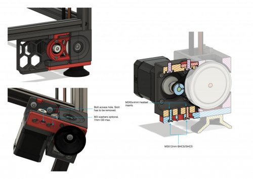
V2.4 Z Drive Motor Tensioner Mod
A Team Dropbear Production
V2.4 Z-Drive Motor Tensioner Mod
Mod that replaces the motor tensioner assembly in the z drive to make it better braced and eliminates chance to rotate/twist when you tension and potentially when the drive operates. The stock motor tensioning had the tendency to flex if not tightened/installed carefully, causing the closed loop belt to easily rub against the pulley flanges. I prefer being able to lock down the entire z drive as a single unit, hence the design choices.
Unfortunately, the skirt geometry changes, so you will have to reprint the front skirts entirely. Besides that, you only need to reprint the motor bracket and the base plate for this mod.
For this reason, this mod is entirely OPTIONAL. Perhaps consider it if you are starting a new build or you wish to improve over the current z drives and are willing to print more plastic.
Installation
1,135 downloads
-
(0 reviews)
0 comments
Submitted
-
(0 reviews)
0 comments
Submitted
-
Roller Brackets
This is a pair of brackets for the stock Voron 2.4 for the purpose of being able to easily roll the machine onto its side.
These mount onto the 2020 on the bottom corners with M3x12, and a V2.2 handle (or 5 cm depth
153 downloads
(0 reviews)0 comments
Submitted
-
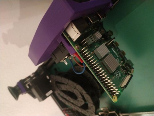
Raspberry Plug Panel
Voron 2.4 Raspberry vertically installed in plug panel
For the DD11 version I used this reference: SCHURTER DD11.0113.1111 Many other versions of SHURTER DDXX plugs are compatible. Check out sizes on datasheet.
Instructions
Put three M3 threaded inserts in the back of the panel. Install the pi on the bracket with three M2x10 self tapping screws. Pass the USB cable(s) for inner components such as SKR before attaching the bracket to the panel. There is a notch on the side of the opening for the raspberry to that purpose. Use three M3x8 to attach the bracket to the raspberry. The rest of the installation is pretty similar to the original bracket: check the official manual.
17 downloads
(0 reviews)0 comments
Submitted
-
(0 reviews)
0 comments
Submitted
-
(0 reviews)
0 comments
Submitted
-
USBCameraMount
This is my contribution to the awesome Voron Community!
It's a camera mount for a WANSVIEW 1080p USB Camera. The distance between the screw holes is 15mm so if you have a camera that has this kind of mounting solution then it might work out for you
Items needed:
2 M3x8 Bolts 2 M3 Slide-in Nuts / T-nuts Assembly:
Print part Remove stock mount from camera Install camera on mount Put nuts into the frame slots Screw on the mount Route the wire through the frame Plug into RPi Enjoy!5 downloads
(0 reviews)0 comments
Submitted
-
Voron V0 Exhaust And LED Mod
Voron V0 Exhaust and LED Mod
No stink, good light
Since the lack of suction on the VO bothered me and, in my opinion, printers should always have light, I developed this mod.
no more stink bright, even light Extraction even without LED lighting
BOM
Exhaust
1 (5 optional) Heatset Insert M3 4 Nuts M3 (optional) 1 Screw M3x8 BHCS 1 Fan 40x40x X (10 or 20mm tail) 4 scrwe M3x X (depending on the fan) LED Light
4 Heatset Insert M3 4 Screw M3x12 BHCS 4 Screw M3x10 BHCS 2 x 10cm LED Stripe 24V 60LED/Meter Build
Exhaust
The exhaust can be exchanged
153 downloads
(0 reviews)0 comments
Submitted
-
Keystone Jack Filtered Mains Panel
Add a Keystone Jack to the Filtered Mains Panel
Modified rear skirt files necessary to add a keystone jack to your filtered mains plug panel.
Files provided for 250, 300, 320 and 350mm builds.
Print the panel along with rear_skirt a and b that corresponds with your build size.
175 downloads
(0 reviews)0 comments
Submitted
-
320mm Build
Voron 2.4 Bottom Skirts for a 320mm build frame.
These bottom skirts have been modified to fit a 320mm build (frame footprint of 480mm x 480mm).
If you use the standard rear plug panels (filtered mains or regular) then print the skirts as provided.
However, if you want to add a keystone jack to the filtered mains rear panel then print one each of the front skirt and head over to my other mod for the rear skirts.
Front View (the awesome accented front panel by Mjoaris is shown but this works with the standard panel as well)
Side View
Rear View
7 downloads
(0 reviews)0 comments
Submitted

-
Most Actively Discussed Mods
-
Hottest Files!
.thumb.jpg.2c879d60315f8d86612bb06a137c204a.jpg)