-
TeamFDM.com is an UNOFFICIAL companion site for the DIY Voron 3D printer community. For official docs and final source of truth, visit the Official Voron Discord or the Voron Github
Printable Voron User Mods
Voron User Mods, or "UserMods", are a collection of community created and Team FDM curated modification for Voron Printers. All of these mods are available on the VoronUsers Github repo and unless otherwise specified follow the Voron communities GPL3.0 Licensing. Use any Mods at your own risk, if you make modification please share them on the VoronUsers repo.
Mod Authors: Have a Voron mod? Upload it at TeamFDM.com and let us know you're the author. We will ensure you can update and curate your files for more feedback! Please include tags for what Voron, or extruder your mod is compatible with.
652 files
-

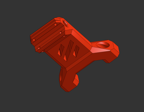
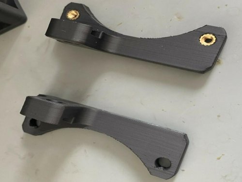
Short Z Joints
Shorter Z joints for Voron 2.4
This mod reduces the size of the Z joint stack by 12.5mm.
The intent is to increase gantry stability by reducing the leverage on the Z ball joints while throwing the toolhead around.
This is only tested with microswitch XY endstops. There is no hall effect magnet slot, though you may be able to affix one to the upper right screw head.
To use this mod, you will need:
4x M5x30 SHCS/BHCS
4x M5x20 BHCS
4x M3x20 SHCS
4x M5 nylon lock nuts (optional*)
You can use standard M5 nuts as per the original config, however I prefer nylock nuts here.
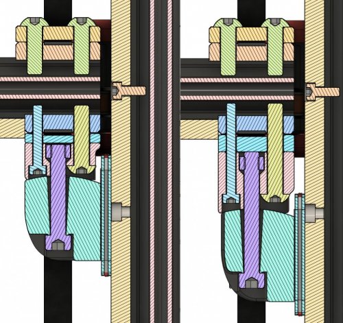
Side by Side
Cross Section
121 downloads
(1 review)0 comments
Submitted
-
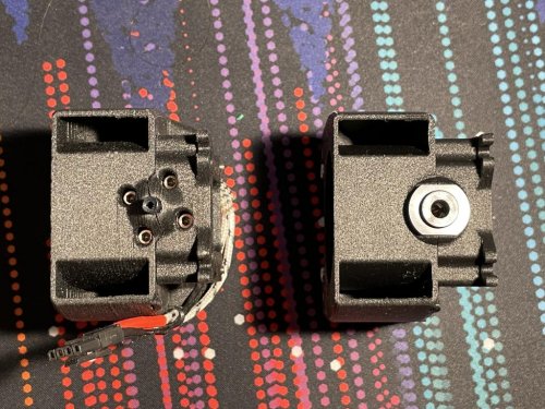
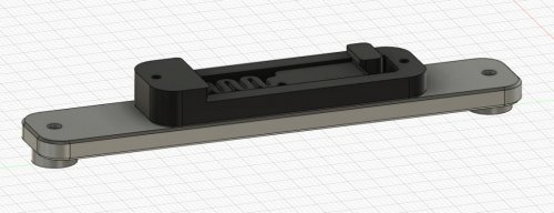
V0.1 Movable Pulley Z
V0.1 Movable Pulley Z Drive Mod
There already are belt-driven mods like theFPVGeek's V0 Z Belt mod and MathematicalPotato's adapted version for V0.1. This is my attempt to combine the timing belt with a movable pulley system.
M4-like driving gear(1:4) with movable pulley on Z bed(1:2), resulting in a 1:8 speed ratio, provides higher torque and step resolution. The bed doesn't drop when the Z motor is disabled. Using a NEMA14 stepper motor (no tight restriction in length) provides another path for V0 to V0.1 upgrade by reusing the Z motor. BOM (Some can be obtained from the original setup)
Fasteners
1 x M2x10 Self Tapping Screw 2 x M3x6 BHCS 11 x M3x8 BHCS 2 x M3x10 BHCS 4 x M3x12 BHCS 5 x M3x16 BHCS 2 x M3x20 BHCS 3 x M3 Washer 4 x M3 Threaded Insert 4 x M3 Hex Nut 3 x M5x20 BHCS/SHCS 3 x M5 Hex Nut 1 x M5 Washer (about 1mm thick, doesn't have to be accurate) Motion
3 x GT2 20T Pulley (6mm wide / 5mm bore) 1 x GT2 Belt Loop (6mm wide) - 188mm GT2 Open Belt (6mm wide) - about 650mm 8 x F695 2RS Bearing 1 x 5x60mm Shaft 1 x NEMA14 Stepper Motor (LDO-35STH42-0504AH, others might also work) Mechanism
As shown in the following figure, the belt drive on the motor is a 20T:80T system.
The driven belt path with constant belt length is a movable pulley system with the two belt ends fixed at the upper and lower parts of the frame.
Instructions
Assembly of Each Component
Note the places that need threaded inserts. You can pre-apply them.
M4-like driving gear
This is very similar to Voron M4 extruder. Just mind the placement of the F695 bearings. You can refer to Nero's video guide for details about assembling Voron M4.
The 80T_gear_7mm.stl provided is a thinner version of the M4 toothed gear with 7mm of tooth width instead of 9mm to save a little weight and space. Both should work here.
Bed Holder
Top Idler
Top Endstop Mount
Use the stock Z endstop and the two M2 self tapping screws.
Assembly
Preload 2 M3 nuts at the marked slot on page 32 of the manual.
(Note: If you don't want to take the frame apart, it can be mounted without these two nuts but it may be less rigid. Don't tighten the belt too much then. NOT TESTED!)
Make a loop on one end of the belt and press it into the printed part. Then mount the printed part to the frame with 2 M3x8 screws.
Mount each component to the frame (don't fully tighten up yet). There should be preloaded nuts if you followed the V0.1 manual. The two upper components and their nuts can be slid in from the top.
Route the belt path as shown in the mechanism figure.
Slightly adjust the position of each component so the bed holder is at the middle of the extrusion and the four marked segments of the belt are as parallel to the Z rails as possible.
Belt tensioning.
First mount the top endstop holder about 2-4mm lower from the top horizontal aluminum extrusion. Then route the belt end through. While holding the belt end, press the printed cover on and lock it with two M3x6 BHCS. Make sure the belt doesn't slip out.
If the belt is still loose, pull the endstop holder upward to adjust the belt tension.
(Note: As marked in the figure, keep the top idler mount and endstop mount below the bottom of the horizontal aluminum extrusion, or the mini-AB might crash into the screw heads or printed parts.)
Klipper Settings
Old format (1.8 degree motor and 16 microsteps): [stepper_z] step_distance: 0.0015625 New format: [stepper_z] rotation_distance: 40 gear_ratio: 80:20, 2:1 Photos
Here's a video of testing the bed motion:
Changelog
2021-08-26
Initial release264 downloads
-
SW FanMount No Tape
Switchwire Fan Mount without using Tape
No change to any required file is required. I just wanted an easy way to mount the 60x20 fan without using tape like suggested in the manual.
Required hardware
1x M5x10 BHCS 2x M3x25 SHCS 2x Heat Set Insert
102 downloads
-
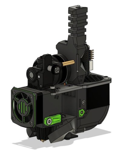
Phaetus Dragonfly BMO Afterburner
Afterburner Toolhead for the Dragonfly BMO
Phaetus
Zodiac
94 downloads
- christophmueller
- dragonfly
- (and 1 more)
(0 reviews)0 comments
Submitted
-
Magnetic Panels
Magnetic Panels
This mod allows for the easy removal of the panels on a V2, ideal for switching between ABS and PLA printing. This mod assumes a panel depth of 6mm, either from a 6mm panel or a 3mm panel 3mm foam tape. It will not hold the panels against the frame without this thickness.
BOM (for top and side panels)
Material Quantity 6x3 Magnets 72 M3x8 SHCS 24 M3 Roll In or Hammerhead T Nuts 24 VHB Tape To reduce the number of magnets required, it is possible to install just two or even one per printed part. This has not been tested and the hold strength unknown.
Assembly
Mount Assembly
Pressfit the magnets into the housing. Use the M3x8 SHCS and T Nuts to secure mounts to the frame.
It is easiest to install using the regular panel clips to hold the panel in position, this allows the mounts to be positioned with some clearance to the panel allowing smoother attachment of the system following installation. To make full use of this added convenience, fully complete installation of a single clip before repeating the procedure for the remainder on each panel.
Cap Assembly
Pressfit the magnets into the housing ensuring the poles are aligned between the mount and cap. Apply the triangular section of VHB tape and with the panel in position on the frame lower the magnet side into position before pressing the tape firmly against the panel.
The panel can now be pulled straight off the frame for removal, before being replaced with as much ease.
230 downloads
- bobbleheed
- v2.4
- (and 1 more)
(0 reviews)0 comments
Submitted
-
BTT 24V UPS Metal DIN Mount
This is a mount for the BTT 24V UPS using the sturdier metal DIN mount.
Metal
12 downloads
-
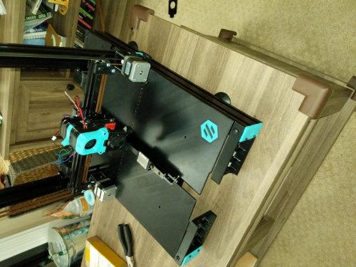
Sw Lightbar
Switchwire Lightbar
Here is my Switchwire light bar. Its a simple, 3 piece print that attaches to the front with some VHB and two M5x10 bolts.
Enjoy!
23 downloads
(0 reviews)0 comments
Submitted
-
Octopus DIN Rail Bracket
A DIN Rail bracket for BTT Octopus board - Voron 2.4
This is a DIN Rail bracket for Bigtreetech Octopus board.
Use default pcb_din_clip.stl x2, and print two parts and secure with m2 self-tapping screw.
Octopus board can be secured to this bracket with M3 screw, without nuts.
STL:
STL
CAD:
CAD
390 downloads
-
FYSETC Spider Metal DIN Mount
This is a mount for the FYSETC Spider using the sturdier metal DIN mount. Two versions are available:
The standard
7 downloads
(0 reviews)0 comments
Submitted
-
RPI Metal DIN Mount
This is a mount for the Raspberry Pi 3/4 using the sturdier metal DIN mount.
Metal
11 downloads
(0 reviews)0 comments
Submitted
-
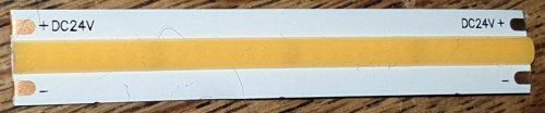
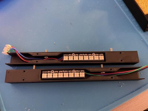
V0 Clippable Ledmounts
V0 clippable Caselight LED Mounts
This LED strip mount is sutable for led strips with a width of 8 - 12 mm, but was made for these 24V COB Led strips.
Since they come in segments of 62.5 mm, the strip mounts are 125mm long to fit two of those segments. When using different leds, the slicer scaling function can be used to shorten them. The clips should still work.
Attach the LEDs
The mentioned led strips come with an M3 adhesive pre-applied, which should be the case for most LED strips commonly found online. This adhesive should be sufficient for attaching LEDs to this mount.
How to print them
The clips were made to print upright, but will probably require a brim for bed adhesion.
26 downloads
(0 reviews)0 comments
Submitted
-
SW Deck Plate
Printable deck plate for Switchwire
I don't have easy access to the tools for precisely cutting ABS sheets, but I figured I could print them pretty well if I split and dovetailed them. I added a debossed voron logo, for style.
All STLs are oriented face down. I printed in ABS with a brim. Trim the brim and join the halves together. Depending on your material choice, use the adhesive of your choice. You can also just secure them to the rails and have the dovetail hold them together, since they aren't moving parts.
Print settings aren't crucial, but the deboss is 0.6mm, so 0.2 or 0.3 should work just fine if you plan to do the logo in a different color.
46 downloads
(0 reviews)0 comments
Submitted
-
V0 Adafruit Y Rails
Mount Adafruit NeoPixel Sticks on the V0 Y-rail Extrusions
Add controllable RGB(W) LEDs to your V0 No heatset inserts required Compatible with NeoPixel Sticks from Adafruit Large cavity inside the body makes wire management easier Light guides prevent LEDs from blinding you Designed with Timmit99's V0 Umbilical in mind (not required)
_Inspired by the mod from JNP_
BOM
Printed parts (2) Adafruit NeoPixel Stick (8) M2x6 flat head - to mount covers (4) M2x8 SHCS/BHCS - to mount the PCBs (4) M3x6 SHCS/BHCS - to mount the assemblies to the Y-rail extrusions (4) M3 nuts - to mount the assemblies to the Y-rail extrusions (2) JST-XH connector plug 4-position - to allow for easy disconnection (optional) 22awg wire Assembly
Solder wires of appropriate length onto the back of each PCB (VDC, GND, DIN, and DOUT) If using JST-XH as disconnects, solder the other ends of the wires to 4-position (male) connectors - the connector should fit inside the body cavity once assembled Mount the PCBs inside the printed bodies using M2x8s Don't install the printed covers at this stage
Installation
Insert 2x M3 nuts on the bottom side of each Y-rail extrusion - requires partial frame disassembly if already assembled For the wire path, you have two choices: Drill 1/444 downloads
(0 reviews)0 comments
Submitted
-
Wire Grommets
Print 4 pieces. Insert standard heatsets. Use Qty 2 M3x8 SHCS or BHCS. Wire openings for Keenovo standard wires for the bed heater, bed thermistor, ground wire.
64 downloads
(0 reviews)0 comments
Submitted
-
(0 reviews)
0 comments
Submitted
-
MGN7H Shims
Two different thickness shims in case your bearings are not co-planar. Particularly on the Z axis. 0.2mm and 0.3mm thick.
2 downloads
(0 reviews)0 comments
Submitted
-
(0 reviews)
0 comments
Submitted
-
Strain Relief W Microfit
Strain Relief to Mount a Microfit 10 pin panel mount connector. Pics have bent cable tie from previous iteration, for printability without supports the STL included prints without support in your slicer. The hole for the connector has a V shaped built-in support that must be cut away to insert connector. Easily snips away with your flush cutters.
9 downloads
(0 reviews)0 comments
Submitted
-
(0 reviews)
0 comments
Submitted
-
FlyF407ZG
Voron 2.4 Hinge Mod for 3mm Doors with 3mm Foam This is designed for 3mm door panels with 3mm of foam. I used the laser cut panels from Printed Solid which are 3.175 (1/8
2 downloads
(0 reviews)0 comments
Submitted
-
Microswitch Endstop
Voron 2.4 XY Microswitch Endstop for PCB
POD for use with the Microswitch endstop pcb board for X and Y axes.
Check Microswitch_Endstop for the microswitch pcb.
33 downloads
(0 reviews)0 comments
Submitted
-
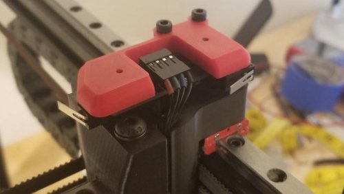
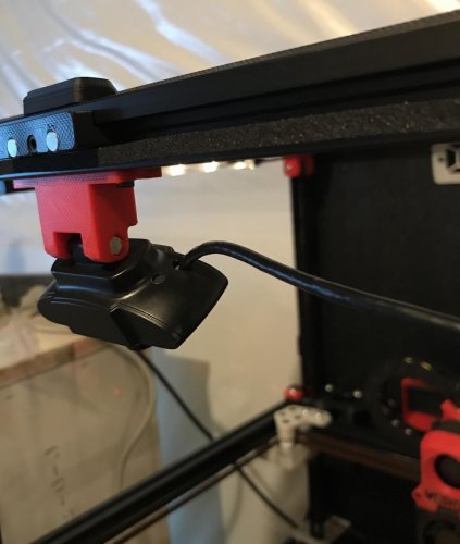
WansviewCameraMount
Wansview 1080p Webcam Mount
This is a mount designed for a resonably priced webcam that's an alternative to the common Logitech choices. The mount is designed to interface with the Voron 2.4 spec extrusions and uses common mounting hardware (2x m3x8 SHCS or BHCS, 2x m3 spring nuts).
Installation:
Remove the black sticky covers indicated by the two arrows Remove the mounting hardware with a phillips head screwdriver
Install the new mount reusing the OEM hardware; position as indicated so your image is oriented correctly (note: get the screw snug enough to hold the camera in place by friction yet still allow you to make small adjustments after install).
install centered on top extrusion with your choice of m3 spring nuts and m3x8 screws. Enjoy seeing your printer printing
77 downloads
-
Duet 3 6HC Din Bracket
Please use the generic PCB DIN Clip and mount these on top.
Image coutersy of medicusdkfz
6 downloads
(0 reviews)0 comments
Submitted
-
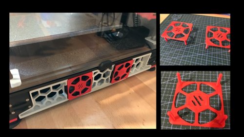
60mmFanCover
60mm Fan Cover for Controller Fans
I took inspiration from StvPtrsn to create an accent cover for the 60mm fans cooling the electronics enclosure. His design is integrated with the skirts and would likely be much more structrually sound; my goal was to make a simple cover that you can insert from the outside without flipping the printer over. It is attached with a small quantity of 3M VHB tape in each of the corners.
Installation:
Apply a small piece of VHB tape on the body of the fan in each of the four corners Insert the pegs of the cover into the fan holes Hold for 30 seconds to give the VHB tape time to bond52 downloads
(0 reviews)0 comments
Submitted
-
(0 reviews)
0 comments
Submitted
.thumb.jpg.8e84033ccda44c57febd99ef7338ef1f.jpg)
-
Most Actively Discussed Mods
-
Hottest Files!
.thumb.jpg.2c879d60315f8d86612bb06a137c204a.jpg)