-
TeamFDM.com is an UNOFFICIAL companion site for the DIY Voron 3D printer community. For official docs and final source of truth, visit the Official Voron Discord or the Voron Github
Printable Voron User Mods
Voron User Mods, or "UserMods", are a collection of community created and Team FDM curated modification for Voron Printers. All of these mods are available on the VoronUsers Github repo and unless otherwise specified follow the Voron communities GPL3.0 Licensing. Use any Mods at your own risk, if you make modification please share them on the VoronUsers repo.
Mod Authors: Have a Voron mod? Upload it at TeamFDM.com and let us know you're the author. We will ensure you can update and curate your files for more feedback! Please include tags for what Voron, or extruder your mod is compatible with.
652 files
-

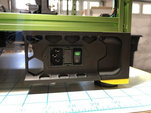
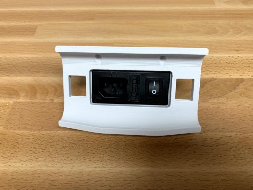
Trident Schurter Power Inlet
Trident Inlet Skirt For Schurter DD11.0124
This is a modified inlet skirt for VORON Trident to install a Schurter DD11.0124 or similar power inlet.
Print using standard VORON print settings. You'll need the same 2 heatset inserts and 2 FHCS screws as the stock filtered inlet to mount this.
17 downloads
(0 reviews)0 comments
Submitted
-
Front Idlers
Longtime Testing Phase! Update (02.09.21): STL's available for testing! Please print and report issues! Update (03.09.21): Added6,915 downloads
-
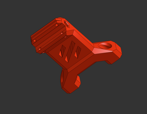
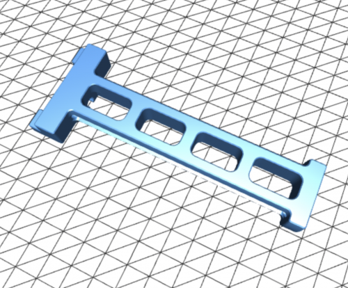
Stiffer DinMount
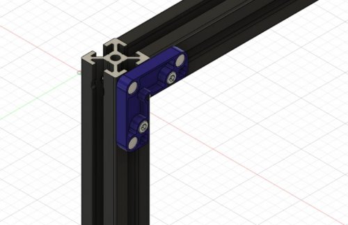
Stiffer DIN Mount
Credits:
Voron-Team: Its the default generic DIN Mount, but modified! Printing:
Default voron settings, correct orientation, no supports needed! Bom:
2x M2x10 Self-tapping Screw Description:
Stiffer generic Din Bracket (same as the one for the pi, but it sits much tighter on the din rail. I found the voron ones a bit wobbly on the din rails) You can use this bracket for everything else. Pictures:
232 downloads
(0 reviews)0 comments
Submitted
-
Exhaust 90
Exhaust 90° Mod (Guided max angle radius for smooth filament sliding)
Credits:
Voron-Team: Its the default 2.4 Exhaust, but modified! @falo2k: Magnetic Grill Cover (Awesome guy, my Grill Cover is exactly his Grill Cover, only with a recessed filament hole, to match the Exhaust 90° Mod.) So all credits to him! Printing:
Default voron settings, correct orientation, no supports needed! Bom:
6x M3 heat inserts 4x M3x25 SHCS (Fan Screws) 2x M3x8 BHCS (Grill Screws) 4x 6x3 Magnets (Grill) 4x 6x3 Magnets (Cover) Foam Tape, please check falo2k for this Magnetic Grill Cover PTFE Tube (3mm ID / 4mm OD) 2x Mount Pieces Description:
Exhaust Mod with as less as possible ptfe tube bending. The ptfe tube is guided. I highly recommend an 4mm OD and 3mm ID ptfe tube. But all other ptfe tubes fits either. The magnetic cover parts are a nice touch. Housing: Only modified for better printability. So no supports needed and it's easy printable. You don't have to use this whole set. The housing is compatible with all331 downloads
(0 reviews)0 comments
Submitted
-
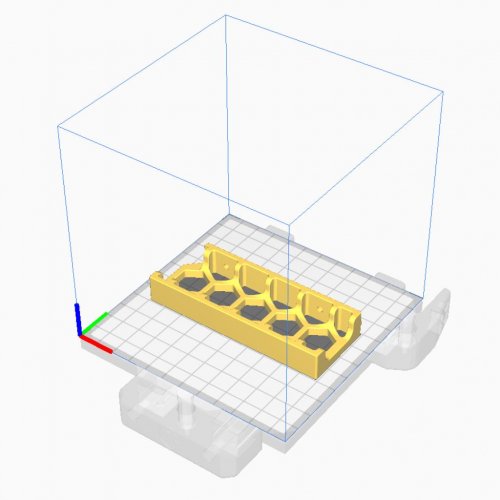
Wagomount 221
Wago 221 DIN Mount
Credits:
Voron Team :-) Printing:
Tolerances are very tight, print only with calibrated flowrate Default voron settings, correct orientation, no supports Bom:
2x M2x10 Self-tapping Screw Description:
Simple design for 1/2/3 x 221 5-port wagos. I didn't found anything here that is mountable to din rails, so i made one simply. The wagos are sitting in there pretty extreme, so you don't need to worry about opening66 downloads
(0 reviews)0 comments
Submitted
-
Misumi Led Corners
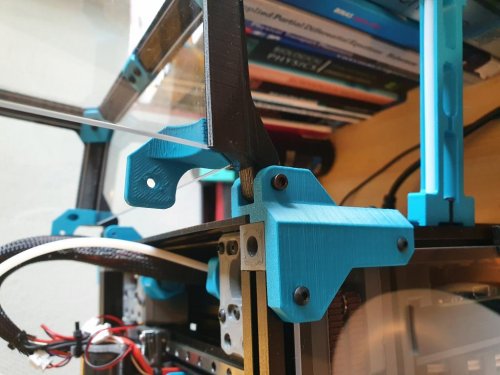
Misumi LED Corner Clips
Credits:
Eddie from the Voron-Team (From his awesome Misumi Led Clips) You get his LED Clips in Discord, he didn't published it to Voronusermods sadly :-( Printing:
Default voron settings, correct orientation, no supports Bom:
Nothing Description:
Corners for the awesome Led Clips from eddie, to hide the wires and one blanklet. No need to cut or recable your wiring, this clips are meant to hide already existing cables. You will find out how it works once you print and try it :-) You can modify their Z-Size as you need, simply scale it. Don't scale below 75% and above 150%. Below 75% the wires will probably not fit on the exit. And above 150% it will just have an big wire exit and will look weird. Pictures:
213 downloads
-
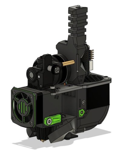
ADXL Skirt Dupont
ADXL Skirt Connector mount (Dupont Version)
Credits:
@alch3my: The plug is based on his skirt insert base, which works amazing btw. Printing:
Tolerances are very tight, print only with calibrated flowrate Default voron settings, correct orientation, no supports Bom:
2x m3x8 or m3x12 screws. 3x 3-pin Dupont 3x 4-pin Dupont 1x 8-pin Dupont (for adxl itself) Some cables (im using 30 20cm) Description:
Should be self explanatory in the pictures! The ADXL Dragon mount is available here: https://github.com/Ramalama2/Voron-2-Mods/tree/main/ADXL_Dragon_Plug Pictures:
269 downloads
(0 reviews)0 comments
Submitted
-
(0 reviews)
0 comments
Submitted
-
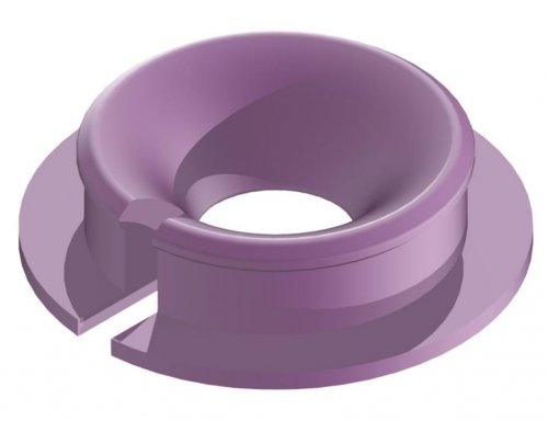
Bedhole Plug
Buttom Plate Bedhole Plug
Credits:
Everyone that can draw a Circle :-) Printing:
Default voron settings, correct orientation, no supports Bom:
Nothing Description:
It's by default for Ø15mm hole on a 3mm plate, but you can simply scale it in your slicer to your needs. Pictures:
56 downloads
(0 reviews)0 comments
Submitted
-
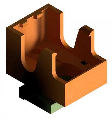
ADXL Dragon Plug
Adxl Mount Heatblock (Dragon Version)
Credits:
@tzeman: https://www.thingiverse.com/thing:4897289 (V6 Plug) He inspired me for this Dragon Version! Printing:
Tolerances are very tight, print only with calibrated flowrate To be safe, scale it to 102% in all dimensions. (It's designed to be scaled between 100142 downloads
(0 reviews)0 comments
Submitted
-
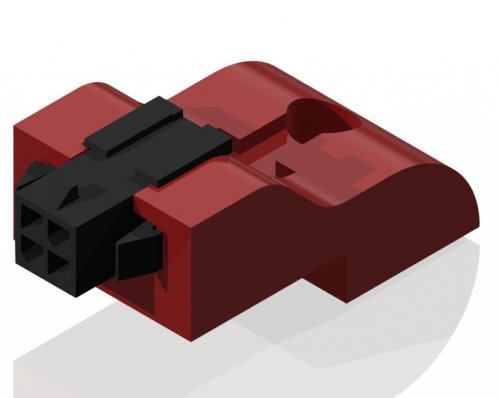
AB Plug Microfit
AB Motor Plug (Microfit)
Credits:
Myself xD Printing:
Default voron settings, correct orientation Supports are needed (Check Pictures below) Bom:
M3x8 M3 T-Nut Microfit 3.0 4-Pin Description:
LDO motor steppers comes with that prewired steppers (which doesn't have a plug), so this is exactly for making a24 downloads
(0 reviews)0 comments
Submitted
-
AB Plug JST XH
AB Motor Plug (Jst-XH)
Credits:
Myself xD Printing:
Default voron settings, correct orientation Supports are needed (Check Pictures below) Bom:
M3x8 M3 T-Nut JST-XH 4-Pin Description:
LDO motor steppers comes with that prewired steppers (which doesn't have a plug), so this is exactly for making a74 downloads
(0 reviews)0 comments
Updated
-
Picam Corner
Picam corner mount
About the only place I found to mount the picam with a view low down of the bed. This was inspired by the v0 design by xbst
Hardware
A single m3x8 bolt and t-nut A suitable length of picam ribbon cable
270 downloads
(1 review)0 comments
Submitted
-
LED Bar Clip
This simple LED clip allows you to mount LED Strip (16.6mm spacing between LEDs) to your 2020 Extrusion. It has baffles to block the light from shining in your face. Print one per LED!
126 downloads
(0 reviews)0 comments
Updated
-
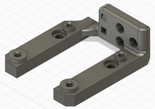
Huvud Chain Mount
Huvud Cable Chain Mount
A mount for the Huvud toolhead board that mounts on the back for cleaner wiring but still allows for the use of a cable chain. Moves the assembly 6mm up to clear the chain at X0 as it rises onto the X joint. Has space for airflow between the motor and the Huvud to keep temperatures reasonable and includes a wire tie spot for wires coming out of the chain. Current only configured for 3-bolt generic chains. Works for both Clockwork and LGX.
Parts Required:
(3) M3 heat set inserts for the chain (3) M3x6 FHCS to mount the chain (2) M3x25 BHCS to mount to the motor (4) M3x8 SHCS to mount the Huvud. Installation:
Remove the printed support. Install the 3 heat set inserts. Remove the upper two screws of the motor. Install the mount with the two M3x25 BHCS. Attach the Huvud with the four M3x8 SHCS. The screws will thread into the plastic. Be sure to check clearance between electrical components and the M3 BHCS screws underneath Attach the chain with the three M3x6 FHCS. Designed for the Trident but will also work on a V2.4, just be conscious of clearance to the Z chain.
31 downloads
- 120decibell
- v1.8
- (and 1 more)
(0 reviews)0 comments
Submitted
-
TophatHingeV0.1
I really like the design of the tophat of the V0 but wanted to be able to open and close it easily.
This is a hinge for the tophat of the V0, without changing the aesthetic. It uses modified panel mounts and tophat parts. I've added panels mounts for thicknesses of 2, 2.5 and 3mm. Also the lower corner clips are adapted to allow for the rotation. All parts can be printed without support.
Printed and tested: the tophat is relatively stable and stays in the open position.
Requirements:
4 x M3x20
6 x M3x12
1,071 downloads
(0 reviews)0 comments
Submitted
-
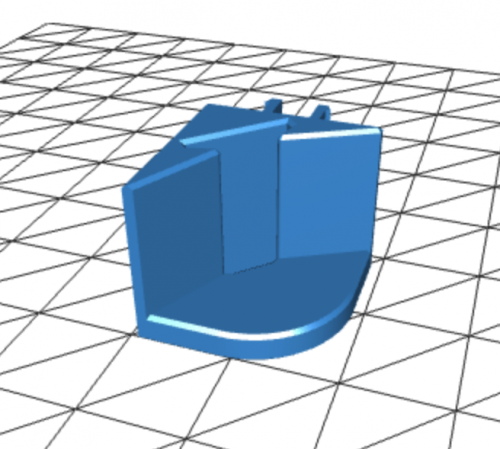
Block Handle V0.1
This is a simple handle design that replaces both side top most panel mount clips. The idea was to make a handle that doesnt require nuts to be added to the frame of the v0.1. Uses a single M3x12.
12 downloads
(0 reviews)0 comments
Submitted
-
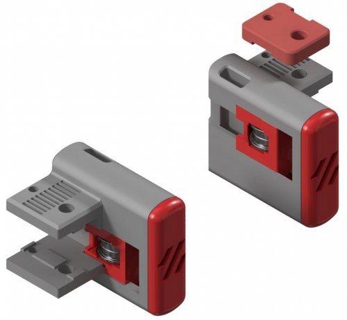
Magnetic Panels
Magnetic Panels
This mod allows for the easy removal of the panels on a V2, ideal for switching between ABS and PLA printing. This mod assumes a panel depth of 6mm, either from a 6mm panel or a 3mm panel 3mm foam tape. It will not hold the panels against the frame without this thickness.
BOM (for top and side panels)
Material Quantity 6x3 Magnets 72 M3x8 SHCS 24 M3 Roll In or Hammerhead T Nuts 24 VHB Tape To reduce the number of magnets required, it is possible to install just two or even one per printed part. This has not been tested and the hold strength unknown.
For larger builds or less rigid panels there are also midspan clips which can be used for additional support.
BOM (per midspan clip) Material Quantity 6x3 Magnets 4 M3x8 SHCS 1 M3 Roll In or Hammerhead T Nuts 1 VHB Tape Assembly
Mount Assembly
Pressfit the magnets into the housing. Use the M3x8 SHCS and T Nuts to secure mounts to the frame.
It is easiest to install using the regular panel clips to hold the panel in position, this allows the mounts to be positioned with some clearance to the panel allowing smoother attachment of the system following installation. To make full use of this added convenience, fully complete installation of a single clip before repeating the procedure for the remainder on each panel.
Cap Assembly
Pressfit the magnets into the housing ensuring the poles are aligned between the mount and cap. Apply the triangular section of VHB tape and with the panel in position on the frame lower the magnet side into position before pressing the tape firmly against the panel.
The panel can now be pulled straight off the frame for removal, before being replaced with as much ease.
Repeat previous steps as required if fitting midspan clips.
753 downloads
- bobbleheed
- v2.4
- (and 1 more)
(1 review)0 comments
Submitted
-
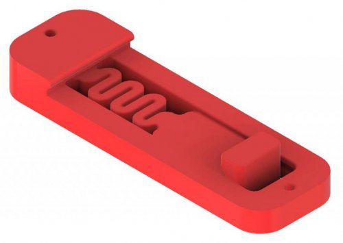
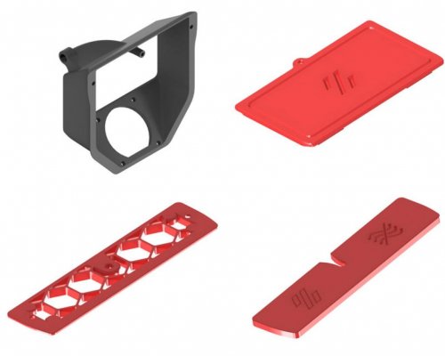
Filament Runout
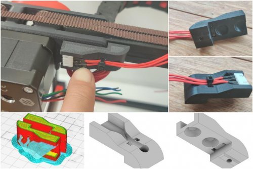
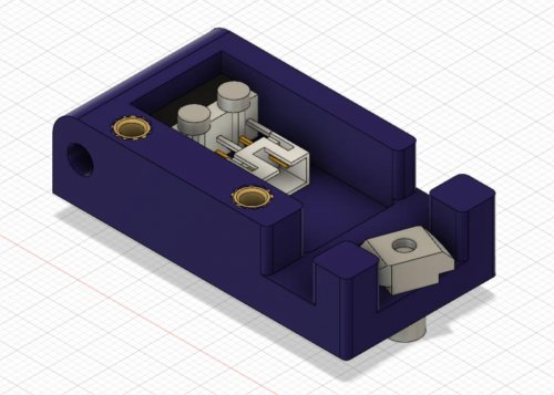
Filament Runout Sensor
This mod replaces the stock bowden retainer with one of a similar profile that hides a runout sensor inside.
BOM
Material Quantity KW10 Microswitch 1 M2x8 SHCS 2 M3x8 SHCS 3 M3 Threaded Inserts 2 M3 Hammerhead T Nut 1 JST 2 OR 3 Pin Housings 1 JST Contacts 2 Glue (CA or Hot) Solder Note:
The KW10 microswitch can likely be swapped out for an Omron D2F-5L switch or other equivalents but this hasn't been tested.
Optionally, wires could be soldered directly to the microswitch negating the need for the JST terminal.
Also two of the M3x8 and the threaded inserts are not required if you do not want to fit a cover over the switch.
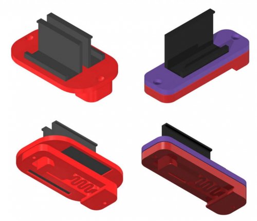
Assembly
Choose the appropriate housing for your printer, either left or right hand (LH or RH) depending on which side you run the reverse bowden to. Print using standard Voron print settings.
If you want to use the housing cover use a soldering iron to insert the threaded inserts into the locations as shown above.
Insert the switch into the housing with the lever opening facing the wider of the openings on the housing sides. Use the M2x8 to fix it in place. The switch should have clearance to fully open inside.
Place the JST terminal inside close to the switch and affixing with glue, bridge the the terminals of the switch and JST with solder in the NO position.
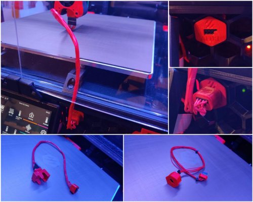
Create a cable to connect the switch to your controller board.
Fit the cover and attach the sensor to your printer using the M3x8 SHCS and the Hammerhead T Nut.
Insert the reverse bowden into the opening on the housing.
Klipper Configuration
Add the file 'filament_runout.cfg' to your config directory via your GUI and add the line [include filament_runout.cfg] into your 'printer.cfg' file. This configuration assumes the use of dual SKR1.3, you may need to change the pin called out by switch_pin: depending on your setup.
If you do not have a M600 macro configured for klipper, change the line pause_on_runout: to true and remove the runout_gcode: section.
114 downloads
(0 reviews)0 comments
Submitted
-
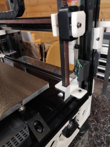
V0.1 Belted Z Drive
Adapted version of FPVGeek's Belted Z Drive mod for the Voron V0.1 which uses the M4 extruder as base.
As with the original, this is a beta release. Still testing and some minor design changes may happen in the future.
NOTICE:
The belt clamp/bed mount part accounts for the 3.2mm shift forward for the bed of the V0.1 when compared to the V0.0. These parts have also been modified for the mid-plate clearance issues that some users faced with the V0.0 version. This design was created to use the same mounting points as the V0.0 leadscrew assembly so use those M3 nut placements in the extrusions.
Design Notes
Designed to take advantage of the 4:1 gearing to prevent the belted Z / bed from dropping when motors are powered off.
Created to be a drop-in replacement of the V0 leadscrew with a minimum amount of disassembly.
Belt intensionally offset to the side, which attaches to and moves the bed, centering the belt. Additionally, this keeps the end-stop screw in the same stock location to retain the use of the stock Z-end-stop
Designed the bottom mount to utilize V0.0 M3 nuts already in the 1515 extrusions. For a V0.1 you'll need to add one extra M3 nut in the back of each Z rail extrusion and two in the rear of the rear bottom extrusion.
Optional bottom panel filler can also be used for this version.
V0-zbelt-BEDMOUNT_MODIFIED_V0.1 has built in supports that need to be removed.
Klipper Stepper Settings:
Old format: step_distance: .003125
New format: rotation_distance: 40 gear_ratio: 80:20 full_steps_per_rotation: 200 microsteps: 16
For an OMC 17HS08-1004S (Spec Clockwork motor) run_current: 0.5 hold_current: 0.4
Assembly Order
These assembly instructions assume you are assembling a new build. If you are converting a prebuilt V0.1 that is using an integrated lead screw you will likely need to disassemble the frame to install extra M3 nuts
Step 1 - As you're building the printer frame, you'll need to check that you have M3 nuts in the following locations and then just get to page 56 of the V0.1 manual.
Step 2 - Put the frame front facing down. Mount the V0-zbelt-BEDMOUNT_MODIFIED_V0.1 to the center of the rear bed extrusion. Then mount the mid panel.
Step 3 - Press two MF105-2RS bearings into the V0-ZBelt-FrontBottom-Bracket. Mount the V0-ZBelt-FrontBottom-Bracket using an M3x10 on the left side.
Step 4 - Place a 20 tooth GT2 pulley at the end of the 70 or 72mm shaft with the set screw end flush with the end of the shaft. Place one of the Printed-PulleySpacer-x2 against the toothed side of the pulley and push the shaft through the MF105 bearings until the printed spacer makes contact. The pulley should now be on the inside of the printer.
Step 5 - Place a GT2 pulley on the motor shaft with the toothed end away from the motor. Exact placement will be adjusted once the 80 tooth gear and 188mm belt are in place.
Step 6 - Assemble the top idler. You can use any of the idlers listed in the original design files. Mount the top idler.
Step 7 - Mount one end of the drive belt into the bottom clamp using V0-ZBelt-BeltClip-Bottom_MODIFIED_V0.1. Route the belt though the top idler and back down to the bed mount. Feed through the bed mount top clamp, secure clamp.
Step 8 - Slide the top idler block upwards to get the belt tension to the tension you'd like and tighten the mount screws. This can be adjusted later more after assembly.
Step 9 - Mount the stepper motor loosely to the V0-ZBelt-Pancake-Stepper-Bracket. Screws will be fully tightened later to tension the 188mm GT2 belt.
Step 10 - Press an F695-2RS bearing into V0-ZBelt-Pancake-Stepper-Bracket. Mount V0-ZBelt-Pancake-Stepper-Bracket with the stepper motor attached to V0-ZBelt-FrontBottom-Bracket.
Step 11 - Place the other Printed-PulleySpacer-x2 onto the open end of the 70 or 72mm shaft.
Step 12 - Mount the 80 tooth gear. If using a printed gear you'll need to remove the flange from a GT2 pulley using pliers or a bottle opener, press the pulley into the printed 80 tooth, and afix with 5 M3x8 BHCS bolts as with the M4 extruder.
Step 13 - Put the 188mm GT2 belt loop on the 80 tooth and 20 tooth mounted to the stepper.
Step 14 - Tighten the 188mm belt be rotating the stepper motor until snug but not overtightened and then tighten the motor mount screws.
Step 15 - Verify the belt is aligned vertically and verify bed moves up and down freely with belt remaining in line.
Step 15 - Mount controller board and pi using either screws or VHB tape.
Step 16 - Wire up Stepper motor
Step 17 - Change Klipper settings to values shown above.
Step 18 - Retension Belt / Top Idler Bracket mount if neccessary.
Step 19 - Test (please start slow) and enjoy.
Addtional Pics:
652 downloads
-
Plug Panel Generic
Voron 2.4 Plug Panel Mod for Generic Unfiltered Modules
OVERVIEW:
Plug panel which fits any modules that have 66mm x 27mm cutout, such as the Delta 06A2 and Qualtek 761-18.
4 downloads
(0 reviews)0 comments
Submitted
-
Parametric Spool Holder
Parametric Spool Holder
OVERVIEW:
Spool holder where the length is a parameter, anything from 25mm up to ~150mm is supported.
179 downloads
(0 reviews)0 comments
Updated
-
V0 Lcdskirt
Voron 0 LCD Touchscreen Skirt
A large LCD touchscreen for OctoScreen or OctoDash.
Bill of Materials
All required parts are listed below. Supplier examples are provided for convenience.
Non-Printed Parts
Additional Non-Stock Parts: Qty Description Supplier Links 1 Adafruit PiTFT Plus 3.2 Touchscreen Adafruit 1 M2.5 x 3.0 mm Heat Set Inserts Alliexpress, McMaster Carr 1 M3 x 50 mm SHCS Alliexpress, Bolt Depot 4 M2.5 x 10 mm BHCS Alliexpress 1 40-pin IDE Extension Cable Amazon Repurposed Stock Parts: Qty Description Supplier Links 12 M3 x 8 mm BHCS Alliexpress, Bolt Depot 12 M3 Makerbeam 1515 T Slot Nuts Alliexpress, Amazon 4 Rubber Feet (14 x 11 x 9) Alliexpress 3D Printed Parts
Qty Description STL Slicer Image 2 Skirt Side A 2 Skirt Side B 1 Skirt Front Left 1 Skirt Front Right 1 LCD Mounting Bracket 1 LCD Face Plate 2 Foot Front 2 Foot Rear All 3D Parts can be printed without support material: ABS, 0.4 mm nozzle, and 0.2mm layers.
Assembly Instructions
Install 4 M2.5 heat set inserts into LCD Mounting Bracket Remove the stock V0 skirt and feet. Install extended feet with 50mm M3 SHCS. Install all Side Skirt A/B parts using the stock mounting T-nuts and M3 x 8 screws. Install the LCD Mounting Bracket using the middle two T-nuts on the front extrusion. Install Front Skirt Left/Right using the remaining two T-nuts on each side of the LCD. Connect the 40-pin ribbon cable to the Adafruit PiTFT Plus. Place the Adafruit PiTFT Plus into the LCD Face Plate. Route the ribbon cable through LCD Mounting Bracket to Raspberry Pi. Secure LCD Face Plate with four M2.5 x 10 screws. Software Configuration
Follow the Adafruit LCD Installation Instructions.
The 3.2
38 downloads
(0 reviews)0 comments
Updated
-
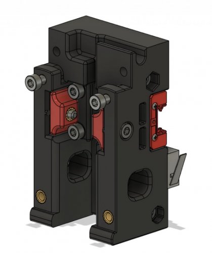
Single MGN9H Carriage
Single MGN9H Carriage
Modified carriage to:
Remove the second MGN9 mount Add optional toolhead X endstop (to allow for umbilical) Make sure your switch lever is in the orientation shown to ensure it triggers properly against the XY joint.
108 downloads
(0 reviews)0 comments
Submitted
-
Bed Fans
Macros and Usage
See bedfans.cfg or bedfans-dualcontrol.cfg* for klipper macros.
1) Place the .cfg file in the same directory as your printer.cfg file.
2) Add [include bedfans.cfg] to your printer.cfg.
3) Change pin for your fans in the second section. This is intentionally left blank so that it will error if you don't fill it in.
4) Configure the options in the first section:
variable_threshold sets the target bed temperature at which your bed fans will activate. variable_slow sets the121 downloads
(0 reviews)0 comments
Submitted


-
Most Actively Discussed Mods
-
Hottest Files!
.thumb.jpg.2c879d60315f8d86612bb06a137c204a.jpg)