-
TeamFDM.com is an UNOFFICIAL companion site for the DIY Voron 3D printer community. For official docs and final source of truth, visit the Official Voron Discord or the Voron Github
Printable Voron User Mods
Voron User Mods, or "UserMods", are a collection of community created and Team FDM curated modification for Voron Printers. All of these mods are available on the VoronUsers Github repo and unless otherwise specified follow the Voron communities GPL3.0 Licensing. Use any Mods at your own risk, if you make modification please share them on the VoronUsers repo.
Mod Authors: Have a Voron mod? Upload it at TeamFDM.com and let us know you're the author. We will ensure you can update and curate your files for more feedback! Please include tags for what Voron, or extruder your mod is compatible with.
652 files
-

Esp8266 Nodemcu Din Mount
ESP8266 NodeMCU Din Mount
Designed to hold an ESP8266 NodeMCU. ESPs are commonly used to control LEDs using the WLED project. The ESP can be mounted in either direction.
The model included can be mounted to the original 2.4 din clip or the newer Trident din clip.
Printing
Default voron settings No supports needed BOM
Size Qty M3x8 4 M2x10 2 Trident PCB Din Clip 1
18 downloads
(0 reviews)0 comments
Submitted
-
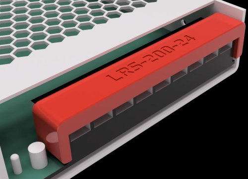
Lrs Screw Terminal Cover
LRS Screw Terminal Cover
Designed to cover the screw terminals for several LRS style PSUs. Other Meanwell PSU may work. Feel free to ping me in discord to add to the compatibility list below.
Pro tip: These are very snug to the point it will bow. This is intentional as it was designed to take some effort to take off.
Printing
Default voron settings No supports needed Compatibility List
LRS-50 LRS-200
491 downloads
(2 reviews)0 comments
Submitted
-
Kirigami LED Bed Front
V0 Kirigami bed front with space for LED
This is a modifaction of the V0 Kirigami front bed made by Kosh42EFG
BOM
Kirigami bed: https://github.com/christophmuellerorg/voron_0_kirigami_bed 1x Kirigami_LED_Bed_Front.stl printed in ABS using standard Voron settings 1x Kirigami_LED_Bed_Front_defuser.stl printed in any white material 2x M3x8 CHCS 2x M3 nuts 1x LED. I use a single neopixel mini button 4x wires for the neopixel (you can use three if this is the only one in the chain) Installation
Install the kirigami bed Wire the neopixel and place in the slot with the wires coming out through the tunnel Add the defuser in front of the neopixel, make sure it is a tight fit to hold it well (print thicker if needed) Fit the Kirigami_LED_Bed_Front.stl to the front of the kirigami bed using the M3 screws and nuts Add configuration change to the printer.cfg in klipper: [neopixel my_leds] pin: PA8 chain_count: 1 color_order: GRB initial_RED: 1.0 initial_GREEN: 0.0 initial_BLUE: 0.0100 downloads
(0 reviews)0 comments
Submitted
-
V0 Belts Holder
Belts Holder
The purpose of this mod it's to ease the printer belt's maintenance.
Usage
Here I needed to replace my x-carriage part. It broke and I glued it for a few days as an emergency.
First, you attach the belts holder to the x-axis inserting it just behind the belts. Then you fix with belt holder's bars the belts, don't tighten too much.
I could remove the x-carriage without having to lose the idlers or have to fight with belts to replace it.
134 downloads
-
Vsw More Robust Belt Paths
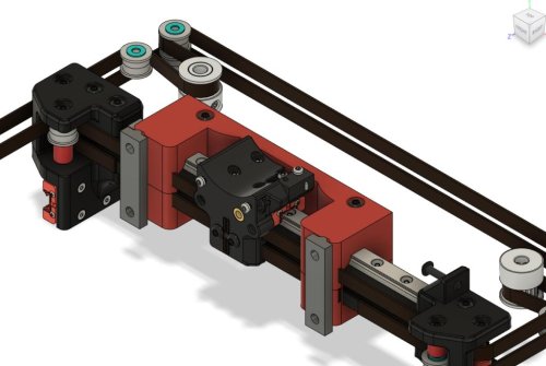
More robust Voron Switchwire belt routing
This mod was created because the original stock parts didn't work well for me. The major part are the moded stepper cages. The stepper cages got tilted usually during tensioning and leading to the axle of the stepper not being parallel with the horizontal plane, which lead to yawning of the belt and increased wear and tear of the belt. Additionaly, the cages parts a and b had the tendency to open up in the bottom, especially when the tensioning screw is one or two mm too long.
The modded version has a through-screw in the bottom and additional screw slot on the top to attach it to the vertical extrusion, to help with proper leveling of the stepper axle. You'd probably be able to address these issues without if you were careful and knew about them. Using this design is just much faster.
Additional mods
The xz blocks have a slot for M5 button head screw that can be used to fix tilting of the blocks w.r.t. the plane defined by the X gantry extrusion. The original blocks have already some measures to prevent this, but apparently those were not sufficient in my case (I was worried about tightening the screws too much, as the plastic already started to give and yet there was still a bit of tilting play).
The upper xz blocks/supports were modded just to help more carefuly define in what position and orientation the blocks should stay. These have the least effect, IMO.
With these, I had printed almost 400 hours without any belt-related issues and the belts look still fresh, no signs of fraying. There exist also similar unofficial mods on Voron discord addressing similar issues but I think this is the most exhaustive version.
Print Instructions
Print Settings: Standard Voron PIF sttings -- at least 40 percent infill, 4 perims, 5 solid layers top and bottom
Quantities: Quantities are noted in the filenames -- each part needs to be printed only in single copy.
Installation
Install should be fairly straightforward, the naming of the parts should follow the original naming, so you could follow the SW manual. Few pictures Please note that the last picture contains an old revision of the upper XZ block (that was reducing the Z travel), but the provided version installs the same way and does not reduce the Z travel. Generally speaking, I suggest tightening the screw attaching the stepper to the vertical extrusion as a very last step.
Overal BOM
6x M5x10 BHCS 6x M5 T-Nut for 3030 2x M3x16 SHCS 2x M3 Threaded Insert (standard676 downloads
-
Vsw More Robust Belt Paths
More robust Voron Switchwire belt routing
This mod was created because the original stock parts didn't work well for me. The major part are the moded stepper cages. The stepper cages got tilted usually during tensioning and leading to the axle of the stepper not being parallel with the horizontal plane, which lead to yawning of the belt and increased wear and tear of the belt. Additionaly, the cages parts a and b had the tendency to open up in the bottom, especially when the tensioning screw is one or two mm too long.
The modded version has a through-screw in the bottom and additional screw slot on the top to attach it to the vertical extrusion, to help with proper leveling of the stepper axle. You'd probably be able to address these issues without if you were careful and knew about them. Using this design is just much faster.
Additional mods
The xz blocks have a slot for M5 button head screw that can be used to fix tilting of the blocks w.r.t. the plane defined by the X gantry extrusion. The original blocks have already some measures to prevent this, but apparently those were not sufficient in my case (I was worried about tightening the screws too much, as the plastic already started to give and yet there was still a bit of tilting play).
The upper xz blocks/supports were modded just to help more carefuly define in what position and orientation the blocks should stay. These have the least effect, IMO.
With these, I had printed almost 400 hours without any belt-related issues and the belts look still fresh, no signs of fraying. There exist also similar unofficial mods on Voron discord addressing similar issues but I think this is the most exhaustive version.
Print Instructions
Print Settings: Standard Voron PIF sttings -- at least 40 percent infill, 4 perims, 5 solid layers top and bottom
Quantities: Quantities are noted in the filenames -- each part needs to be printed only in single copy.
Installation
Install should be fairly straightforward, the naming of the parts should follow the original naming, so you could follow the SW manual. Few pictures Please note that the last picture contains an old revision of the upper XZ block (that was reducing the Z travel), but the provided version installs the same way and does not reduce the Z travel. Generally speaking, I suggest tightening the screw attaching the stepper to the vertical extrusion as a very last step.
Overal BOM
6x M5x10 BHCS 6x M5 T-Nut for 3030 2x M3x16 SHCS 2x M3 Threaded Insert (standard197 downloads
(0 reviews)0 comments
Submitted
-
RGB LED Grid For SB
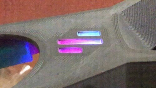
RGB LED grid for the Stealthburner (a.k.a. Rainbow Barf Logo LED)
This PCB, created in KiCad 6.0, is a collaboration between me and tanaes (a.k.a. whoppingpochard). It's a RBG 8× LED grid to be used on the logo of the Voron Stealthburner, to give the user more animation options than a single, boring RGB LED. 😁
Important note: this PCB uses 2.0mm × 2.0mm WS2812B RGB LEDs, they should not be used with RGBW LEDs in the same chain unless you know what are you doing, as they use different data protocols. The usage is possible, but it isn't straightforward. There is information that a workaround for mixing RGB and RGBW LEDs is being developed at the Klipper-led_effect repository, which is what whoppingpochard and I recommend for controlling this board.
Updates
January 16th, 2022: Initial release.
February 18th, 2022: added link for whoppingpochard's Rainbow Barf's repository, and info about Klipper-led-effect developing a solution for mixing RGB and RGBW LEDs. There are little cosmetic differences between that version and the one I've uploaded here, nothing that will change the way it works. Choose whatever suits you better. 🙂
March 17th, 2022: added the KiCad version that was used to design the PCB.
66 downloads
- VinnyCordeiro
- v1.8
- (and 3 more)
(0 reviews)0 comments
Submitted
-
Voron 0.1 - Pi Cam Mount
A webcam mount for Voron 0.1.
Not the best position for a cam but while printing it does its job and it isn't attached to the tophat. It also requires no long cable.
You need the following parts:
- 4x M3 8mm screws
- 4x M2 6mm screws
- 2x Zipties OR 2x M3 15mm screws.
266 downloads
(0 reviews)0 comments
Updated
-
Voron Design Logo STl File
Just thought maybe others might like .stl file as option, Seems to scale nicely.
221 downloads
(0 reviews)0 comments
Submitted
-
(0 reviews)
0 comments
Submitted
-
Voron2.4 GE5C
Voron 2.4 GE5C Z joint
BOM
Screws Size Qty M3x12 4 M3x16 or M3x20 SHCS 16 M5x20 4 Ge5C Bearing 4 M5x1mm spacer 4 If using Halleffect 6x3 magnet 1
First just insert GE5C bearing , it should just pop in
Now if you are using the
1,006 downloads
-
4channel Relay Under Deck Mount
4 Channel Relay Under Deck Mount
Mod to mount a 4 channel GPIO controlled relay in the electronics compartment.
Printing
Default voron settings No supports needed BOM
Size Qty 4 Channel relay 1 M3x8 or M3x6 4 M5x8 2 M5 T-Nut 2
16 downloads
(0 reviews)0 comments
Submitted
-
FIT0729 Camera Housing 2020 rail mount
Housing for a FIT0729 plug&play camera. Top mount Voron 2.4
Printed with Petg Extrudr black matte
96 downloads
(0 reviews)0 comments
Updated
-
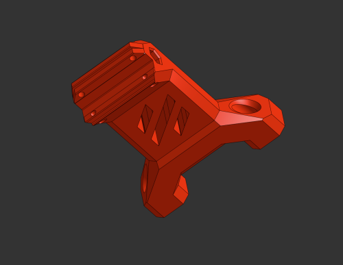
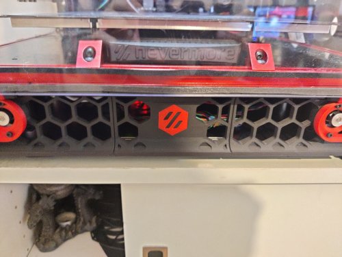
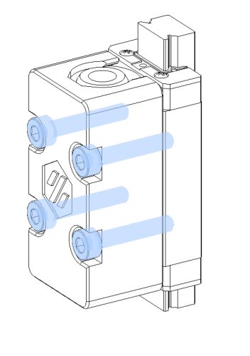
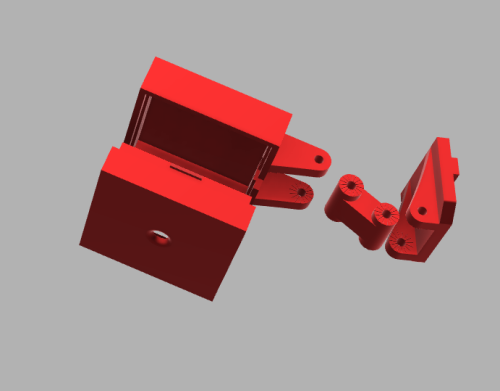
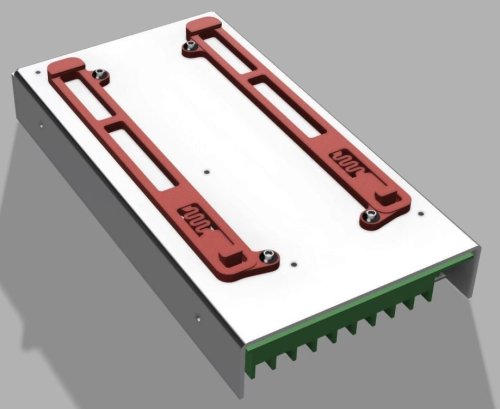
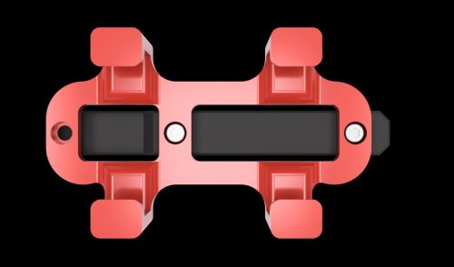
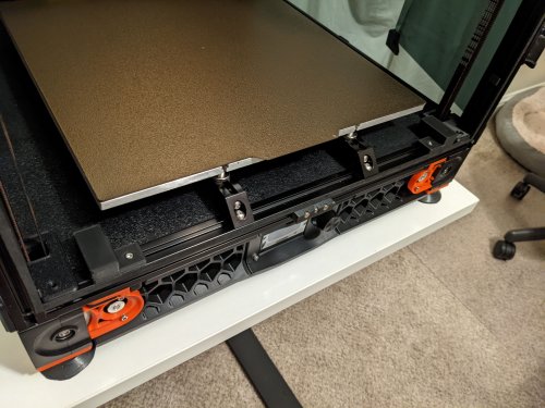
Double DIN LRS200-24 Mounts for Voron 2.4
I'm in the middle of my build and mounting my MeanWell LRS 24V and didn't like the options I found which predominantly seemed to be horizontal with the DIN rail. I wanted something turned 90 and clipped to both DIN rails so I modified the ones from the 2.4 Fusion file to work. I'm still quite new to Fusion so somethings not working for you on it let me know but I've already printed and mounted on my power supply where they snuggly hold it in place.
463 downloads
-
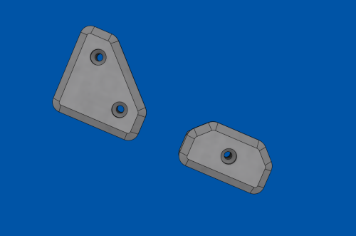
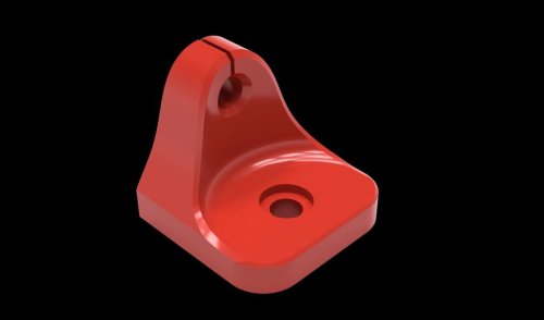
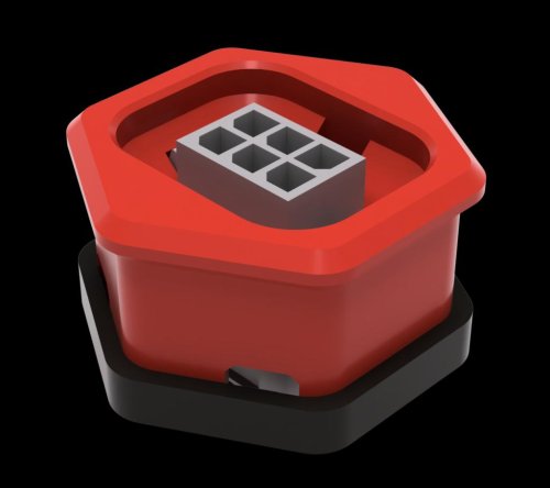
Retainer Hardware for 6mm Glass Enclosure Panels
These are sized for a sheet of 6mm Glass WITH a layer of VHB; the base is 7mm tall and the retainer tab is 4mm thick.
44 downloads
(0 reviews)0 comments
Submitted
-
Voyager Gtx Din Mount
Corsair Flash Voyager GTX Din Mount
Din carrier for a Corsair Flash Voyager GTX. To be able to plug in the USB drive you can purchase a small USB extension cable located in the BOM below.
The model included can be mounted to the original 2.4 din clip or the newer Trident din clip.
Printing
Default voron settings No supports needed BOM
Size Qty M2x10 2 Trident PCB Din Clip 1 Corsair Flash Voyager GTX 1 .5ft USB extension (Optional) 1
0 downloads
(0 reviews)0 comments
Submitted
-
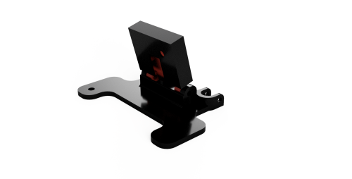
Extrusion Thermistor Mount
Extrusion/Chamber Thermistor Mount
Designed to mount a NTC100K Thermistor Sensor to 2020 extrusions.
Printing
Default voron settings No supports needed BOM
Size Qty NTC100K Thermistor 1 M3x8 1 M3 T-Nut 1
363 downloads
(0 reviews)0 comments
Submitted
-
Microfit 2x3 Skirt Connector Adxl
Microfit 2x3 Skirt Connector (ADXL)
Mod for a Microfit 2x3 connector to be mounted in the bestagons. Typically used for ADXL but can be used as a general connector for anything outside the printer.
Pro tip: I found that adding some hot-glue while installing it into the skirt makes it a bit more robust for unplugging and plugging in.
This is originally based off of this mod. It was modified to not require supports and have a bit tighter fit onto the connector.
Printing
Default voron settings No supports needed BOM
Size Qty Microfit 0430200608 1 Microfit 0430250600 1
260 downloads
(0 reviews)0 comments
Submitted
-
Corner Cable Hide
Top Corner Cable Hide/Cover (LED Wires)
Designed to hide cables that are running around the top corners of 2.4 extrusions behind the z idlers.
They are large enough to fit 3 pin microfit connectors.
There maybe some small loss in z. Don't forget to check your clearances after installing.
Pro tip: It may take some fiddling to get the wires to fit. You will know they are in place when it sits flush to the extrusions without wobbling. Also disable 'Thin Walls/Detect Thin walls' so the mounting ears print cleanly.
Printing
Default voron settings No supports needed BOM
Size Qty M3x8 8 M3 T-Nut 8
557 downloads
(0 reviews)0 comments
Submitted
-
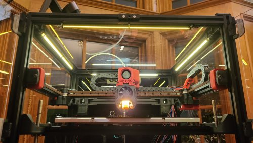
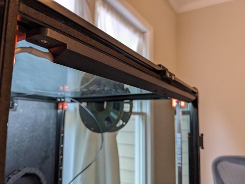
SuperSlim - LED Bar with Simple Bracket
SuperSlim LED
This is a design I'm calling the SuperSlim. It's a super slim LED bar that fits at a 45 degree angle on the 2020 extrusion at the top of your Voron. You print out these small and simple brackets, clip them onto the LED bar and against the extrusion, and presto! You have a gorgeous looking, bright, and simple LED light. Even better these bars use micro LEDs so you get a lot of light diffusion, i.e. no hot spots, and one of the best final looking lights out there for your Voron.
SuperSlim Bracket
The bracket truly makes this design awesome and simple. Here it is in all its simple glory. Print 12 of these. In fact print 20 of these and use them to push/hide your wires tucked into the extrusion slots as well because they're so quick to print, easy to snap in, flexible, strong, sexy looking, and durable. And they're fun to print on your new ABS capable Voron.
Grab the STL or 3MF file attached to this post to print out the bracket using your favorite slicer.
Use 0.3mm layer height for faster prints that are stronger. Use 4 walls to achieve basically no infill. 100mm/s speed should be fine.
Micro LED Bar
Here's a link for the LED light bar on Aliexpress. There are several vendors, so just search 300x6mm LED. Get the Warm White color temperature. Too stark of a bright white is harsh to look at.
300x6mm LED Lights (Pack of 10. About $1.70 each.)
https://www.aliexpress.com/item/32786326547.html
Wiring / Soldering
The light bars are 12V, so to plug them directly into your control board's 24V output, like HE2 (heater 2), so you can control the light from Klipper, you need to wire up 2 of the lights in serial to get 24V. Then wire up the other 2 in serial for another 24V. Then connect those together in parallel to drive off of one heater output.
So connect the + out of HE2 to the + on your first LED bar (LED1). Then connect the - from LED1 to the + on the your 2nd LED bar (LED2). Then connect the - on LED2 to the - on HE2. Go ahead and test out LED1 and LED2 by turning on HE2 using the settings in the section below. Once you're happy, go ahead and finish connecting the last 2 LED bars the same way you did this set of LED bars in step 1 thru 3. Configuring Klipper
You can see it here in Mainsail called "Caselight".
Here is the printer.cfg settings for controlling the LEDs.
[output_pin caselight] # Chamber Lighting - HE3 Connector (Optional) pin: PB11 pwm:true shutdown_value: 0 value:0.06 cycle_time: 0.0002 # with 0.0002 the min is 5%. 7% seems like a good idle state. 40% for prints. over 60% to 100% all seems to be same brightness # with 0.0001 the min is 9%. 12% seems like a good idle state. over 60% to 100% all seems to be same brightness hardware_pwm: True Add some macros as well for convenience.
[gcode_macro LED_ON] gcode: SET_PIN PIN=caselight VALUE=1 [gcode_macro LED_PCT_IDLE] gcode: SET_PIN PIN=caselight VALUE=0.06 [gcode_macro LED_PCT_PRINT] gcode: SET_PIN PIN=caselight VALUE=0.4 [gcode_macro LED_OFF] gcode: SET_PIN PIN=caselight VALUE=0 Then modify your Start / End / Cancel macros so they turn up and down the lights when you start or end your print.
The Start macro...
[gcode_macro PRINT_START] # Use PRINT_START for the slicer starting script - PLEASE CUSTOMISE THE SCRIPT gcode: ;SET_PIN PIN=caselight VALUE=0.4 ; turn on case light LED_PCT_PRINT
The End macro...
[gcode_macro PRINT_END] # Use PRINT_END for the slicer ending script - please customise for your slicer of choice gcode: LED_PCT_IDLE The Cancel macro...
[gcode_macro CANCEL_PRINT] description: Cancel the actual running print rename_existing: CANCEL_PRINT_BASE variable_park: True gcode: LED_PCT_IDLE You should end up with some nice macros that turn your lights on and off at the right time.
This video walkthrough of my serial request will help you get an idea of what these lights look like in a video.
318 downloads
-
LED Light Clip Corner
For use with Eddie's LED_Bar_Clip, this is a 50mm corner piece that hides wire management and fills out the corners. Comes with eyelet for a zip-tie and two M3 loose-fit thru holes for screwing to the extrusion (could modify for clips but would require support to print)
Pieces are 50mm square, on my 250x250 I have 16 of Eddie's clips and one of these on each side. You may need to adjust the size depending on your build, but the FreeCAD file provided should still hold up if you want to adjust the dimensions (I tried reducing to 45mm square and it turned out fine)
Hope this helps with making pretty lights!
~happylittlePCBs
66 downloads
- led
- happylittlepcbs
- (and 3 more)
(0 reviews)0 comments
Submitted
-
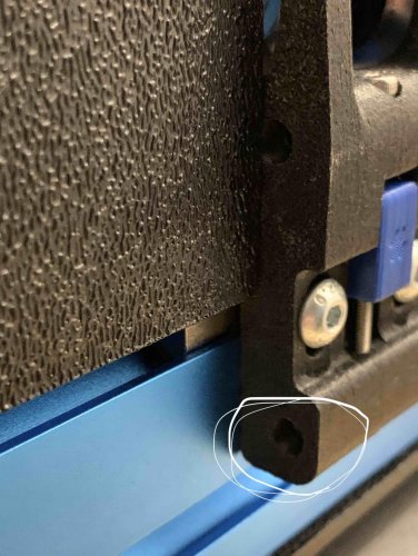
Chamber Wire Caps
I was struggling to find a clean way to wire components I was installing to the front and sides of my chamber, so I designed these wire caps to allow me to route the wiring through to the wiring compartment in a much more convenient location without showing the wiring.
BOM:
3x8mm SHCS x1 3mm T-nut x1 3/8" Rubber Grommet Assembly:
Drill a 3/8" hole in the bottom panel (Do not exceed 20mm from the extrusion) Install the rubber grommet Route the wire through the grommet Install the t-nut Tighten the wire cap to the t-nut There are two versions of the wire cap so you can use this print to route wire from either direction. Just make sure to choose the one that works for your use case.
24 downloads
(0 reviews)0 comments
Updated
-
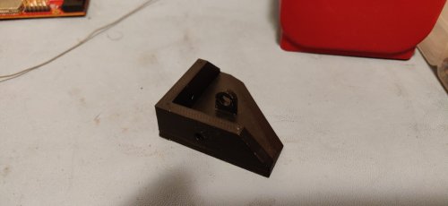
v2.4 45 degree LED mount
This is a two piece LED strip mount. It accommodates 7mm-8mm LED strips and mounts them to 2020 extrusion at a fixed 45 degree angle.
BOM:
Printed Male Mount Printed Male Mount - 1 Printed Female Mount - 1 3mm Socket Head Bolt - 4 3mm T-nut - 4 Strip of 7mm-8mm led lights
Notes:
This was specifically designed to fit my 350x350 build. It would likely need to be scaled down to fit smaller v2.4s I'll add a better wiring photo once I get it cleaned up554 downloads
-
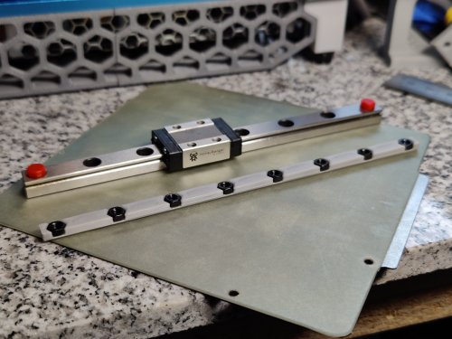
nut adapter for mgn9 rails
This is a simple nut adapter to keep hex nuts in place inside the 15mm extrusion if you're using mgn9 linear rails. This complements the MGN9 X-axis mod for the V0.1. The hole spacing is 20mm center-to-center between each screw hole and 5mm edge to center on either end.
104 downloads
-
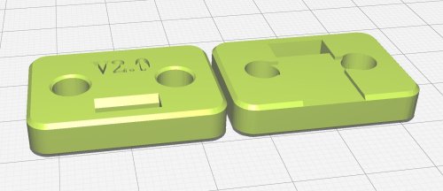
Upper Z Clip Mod V2.0
I'm working on this mod because I only left about an 1 1/2" of belt hanging out of the upper Z clip. I printed it with 100% infill to match other parts printed on a resin printer. I'm hoping others find it useful.
152 downloads


-
Most Actively Discussed Mods
-
Hottest Files!
.thumb.jpg.2c879d60315f8d86612bb06a137c204a.jpg)