-
TeamFDM.com is an UNOFFICIAL companion site for the DIY Voron 3D printer community. For official docs and final source of truth, visit the Official Voron Discord or the Voron Github
Printable Voron User Mods
Voron User Mods, or "UserMods", are a collection of community created and Team FDM curated modification for Voron Printers. All of these mods are available on the VoronUsers Github repo and unless otherwise specified follow the Voron communities GPL3.0 Licensing. Use any Mods at your own risk, if you make modification please share them on the VoronUsers repo.
Mod Authors: Have a Voron mod? Upload it at TeamFDM.com and let us know you're the author. We will ensure you can update and curate your files for more feedback! Please include tags for what Voron, or extruder your mod is compatible with.
652 files
-

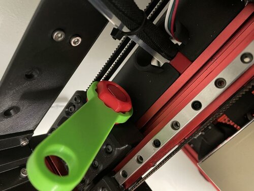
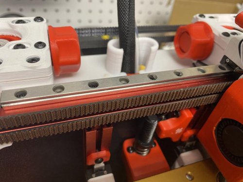
Belt Tension Wrench
Belt Adjustment Wrench
This is a wrench that goes over the AB belt tensioner nuts to help with fine tuning the belt tension.
113 downloads
(0 reviews)0 comments
Submitted
-
Scrubby
Overview
Scrubby is a filament dust scrubber that prevents any dust from reaching your nozzle and burning, causing partial clogs. My nozzle was clogging regularly and I decided to test a dust scrubber, and I have not had another clog for a very long time, so I thought I would make this design public in case someone else can benefit.
Materials needed
8x 6x3 Neodynium Magnets Any cheap, sponge-like material (I cut up part of a scotchbrite kitchen sponge) 2x Scrubby.stl Note: I tested the tolerances in ABS. Due to shrinkage, other filament may make a slightly larger hole. Assembly
Assembly is quite simple; press fit or super glue the magnets into each hole, carefully paying attention to polarity. Cut up your chosen spongy material and fit it into each scrubby half. Place your scrubby halves together, sandwiching the filament between the halves. You want enough sponge to get a nice drag on the filament to make sure it cleans it as best as possible. I put mine right against the bowden retainer, shown in the picture above.
Notes
I included the solidworks part file and the step file in case anyone wants to modify. Make sure to clean the dust it filters off somewhat regularly. It pulls a suprising amount off. Please message me on discord if you have any questions. Happy clog-free printing!
145 downloads
(0 reviews)0 comments
Submitted
-
The Cephalopods Limb
Just another DIN Rail bracket for BTT Octopus board
This is an alternative DIN Rail bracket for Bigtreetech Octopus boards (Normal and Pro-HV), posted this way back in Voron Discord just never uploaded it to VoronUser Mods
Use either 2 of the old style Voron 2.4(r1) r1_pcb_din_clips. or 2of the new trident/r2 ones r2_pcb_din_clips.
Octopus board can be secured to those bracket with M3 screw, without nuts, just gently screw them in as its ah just plastic fitting!
I've also made ah simple Version of the bracket, initially even before the octopus limbs Version, as there where no bracketavailable as i got my Octopus board...
There are also the SVG Files of the Octopus Logo i created, from what i used to extrude the Bracket in Fusion360
STL:
Octopus limb bracket STL
Simple bracket STL
14 downloads
(0 reviews)0 comments
Submitted
-
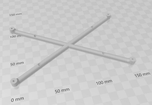
V2.4 Trident Spool Holders
Why?
If you are building Voron 300mm2 or 350mm2, V2.4 or Trident, you will soon discover you need a larger/deeper desk to accomodate your new machine, also if you have 5.5 or larger display mod you will end up with the printer being backed up against the wall and not enough space for the spool holder. After encountering the problem i've started messing with different designns that would provide stable, easily accessible place for the filament spool while keeping the filament path as short as possible.
Print
All parts are printed without supports. Recommended material is ABS/ASA but PETG or even PLA can be used as well. Frame extrusions get hot during long prints under enclosure so be carefull with PLA. Recommended perimeter count is 4 and 5 top/bottom layers with infil from 20% . All parts in STL already have correct orientation, just import and print.
STL File naming:
Classic__part_name.stl - Parts for Classic Voron spool holder design BB__part_name.stl - Ball Bearing Version parts Versions:
1. Ball Bearing Version
2. Classic Voron type spool holder
Ball Bearing Version
This version uses 100mm x 8mm rod for spool core mounting. Provides very smooth motion and virtually no resitatnce to the spool motion. The downside of this design is that the spool can free sping and cause the filament to jump off the spool and entangle.Since my printer is very close to the wall the wall itself servers as a resistance to the filament and prevents any free spinning and filament slipping off the spool.
Ball Bearing version - BOM
S-F-608-ZZ Bearings 1x 10mm x 8mm steel rod with cut internal M4 threads on both ends (easy to find on any mechatronics shop and easy to DIY) 10 M5x10 BHCS 4x M5x16 BHCS 4x M5 Hex Nut
Classic Voron type spool holder
This version uses classic Voron spool holder design adopted to fit the spool holder arm. This design is recommended as it greatly reduces/eliminates the risk of free spinning of the spool and filament slipping over the spool. This version is also simpler/easier and cheaper to make.
Ball Bearing version - BOM
8 M5x10 BHCS 4x M5x16 BHCS 5x M5 Hex Nut 1x M5x30 BHCS 2x 105mm PTFE (4mm OD)
959 downloads
(0 reviews)0 comments
Submitted
-
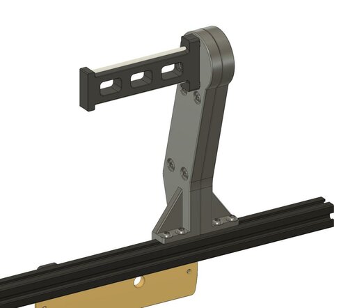
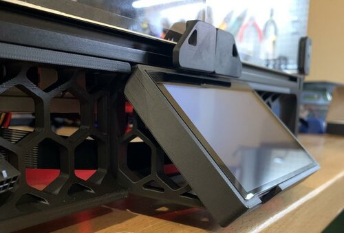
PITFT50 45 Degree Mount
BTT PITFT50 45-degree Mount
This mod is an alternative frame mount for alanho's PITFT50 screen mount. They suggest using the frame mount from sttts, which puts the screen at a 30-degree angle. I found that with the shorter guitar amplifier feet on the Trident and 2.4r2, the 30-degree mount makes the screen assembly too tall to fit under the frame. This mod replaces the 30-degree frame mount with a 45-degree mount, which provides plenty of clearance.
This design was created from scratch, but was heavily inspired by other mods:
roboticator24 - 4-inch Touchscreen Mount jeoje - 4.3-inch Touchscreen Mount sttts - Waveshare 5.5inch HDMI AMOLED Mount This was tested with a BTT PITFT50 v2, but will likely also work with sttts's 5.5-inch Waveshare mount, since the hole pattern is the same.
Bill of Materials
6x M3x8 SHCS 2x M3 T-Nuts alanho's PITFT50 mount Assembly Instructions
Assemble the screen mount Use 4x M3x8 SHCS to attach the frame mount to the screen mount Insert 2x M3 T-nuts into the bottom of the frame Thread 2x M3x8 SHCS into the T-nuts to attach the mount to the frame Printing
I printed with standard Voron settings, but this would probably be fine with fewer walls and less infill. I found this part very prone to warping, so you may want to use a brim or ears.
391 downloads
- CannedBass
- v2.4
- (and 1 more)
(0 reviews)0 comments
Submitted
-
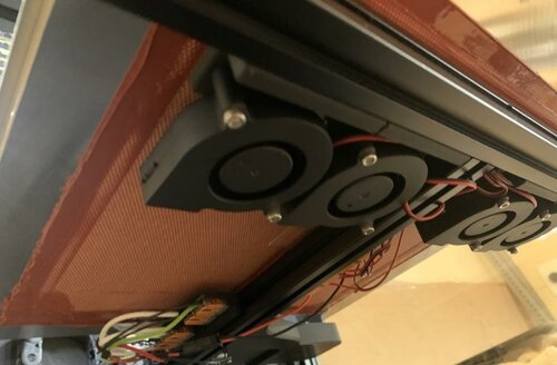
Trident Bed Fans
Trident Bed Fans
Andrew Ellis's Bed Fans, adapted to mount on a Trident. See his mod for some useful macros and more information.
Bill of Materials (per fan):
1x 5015 Blower Fan 2x M3x20 SHCS 1x M3x8 SHCS 2x M3 Threaded Insert Install Instructions (per fan)
Note: Install the printed mount onto the extrusion before attaching the fan. The mounting screw will be inaccessible once the fan is attached.
Heat-set the threaded inserts into the holes in the L-shaped section Add one M3 T-nut to the rear-facing slot of the bed extrusion Use 1 M3x8 SHCS to attach the printed mount to T-nut, aligning the bump in the printed part with the slot on the extrusion. Pass 2 M3x20 SHCS through the fan mounting holes and screw into the threaded inserts to attach the fan to the printed mount261 downloads
(0 reviews)0 comments
Submitted
-
MKS Mosfet Mount
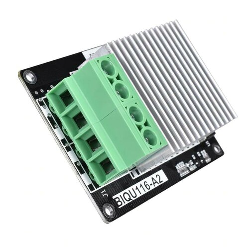
MKS Mosfet Mount
A mount for a BIQU116-A2 MKS Mosfet based on the Trident Raspberry Pi mount. Use an extra pcb_din_clip_v2 to fix it to the DIN rail.
34 downloads
- mikepthomas
- v1.8
- (and 2 more)
(0 reviews)0 comments
Submitted
-
SW Wall Plate
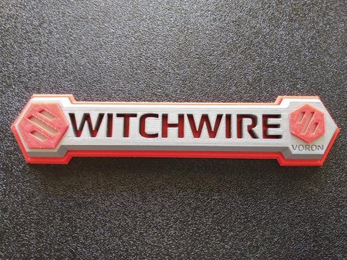
Switchwire Wall Plate
This mod is for pure aesthetics. A Voron Switchwire logo plate to install on the back wall of your printer's enclosure.
(Or optionally on the front grill if no enclosure - but only if you're not already using the LCD mount...)
Note: Overall size is about 225x50 (about 10mm thick)
BOM
(4) M3x8mm BHCS (4) M3xD5.0xH4.0 heat-set inserts VHB tape
Directions
Install inserts in the WITCHWIRE_base
Use backplate_and_drillguide to drill holes in your back panel
Use thin strips of vhb tape to affix the badges into respective recesses on the base (no need to affix base to backplate)
Note: badge tolerances are tight - you might need to sand a bit off the edges of the badges.
Attach to back panel with (4) M3x8 screws (Optional: To use on front grill, affix all parts together using vhb tape, and similarly affix the optional nolcd_grill_mount to the center top of the backplate.)
CAD
OpenSCAD sources are included (it's all I know). They are sparsely commented - make modifications as you wish.
Tip: If you resize the badges, use hundredths of a mm to adjust.
63 downloads
-
LCD Case Mod
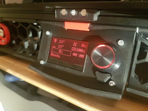
LCD Case Mod
I have made some changes/improvements to the Mini12864 LCD case as follows:
I found the hot melt inserts to be difficult to align straight, on both the rear and front case due to the geometry and space constraints. I have therefore removed them and resized the holes accordingly. For the case rear, I have added M3 threads to the 4 fixing holes, these should print fine with standard Voron printing settings. I have added a lip around the screen cutout to better hide the PCB board behind it. This is simply for aesthetic reasons. I have added an E-stop button cover, taking inspiration from both the previous Voron LCD cover as well as the Prusa i3 design. This allows for both easier prodding of the E-stop button as well as improving the aesthetic of the case (in my opinion). Standard vs. modded design comparison
Please see below the changes between the standard/stock LCD case in the first image, and my modded design in the second.
Installed Case Mod
Installed and working well 🙂
78 downloads
(0 reviews)0 comments
Updated
-
DooMini
DooMini
This is Voron 0.1 mod that improves the insulation of the printer by using double glazed panels and minimal hardware. The New planes help you print full bed size ABS without ever worrying about warping. I get almost 60c chamber temperature with DooMini. (The temperatures are measured at the base of the chamber which is usually the coldest area). Almost forgot ... it looks way Cooler 😛
For All STL file as we as manual and instructions visit https://github.com/TigranDesigner/Voron-Mods/tree/main/DooMini or download directly here.
1,713 downloads
-
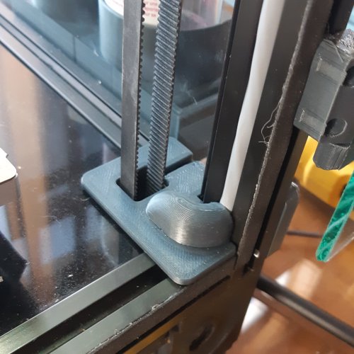
Z Belt Covers with Wire Management - hide wires from extrusion groove to base
Two part wire duct that replaces the Z belt covers and directs the wires away from the belts under the deck plate. No need to modify the original deck plate. For easy use, pass wires before assembling with CA glue
the upper duct has print support integrated in the part
290 downloads
(0 reviews)0 comments
Updated
-
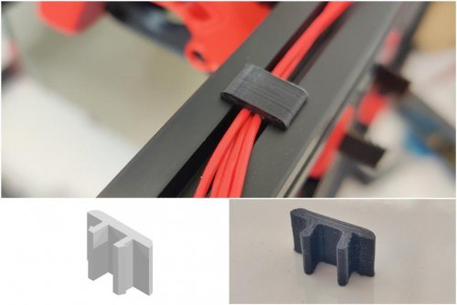
Misumi Cable Clip
Misumi Cable Clip
Credits:
Eddie from the Voron-Team (From his awesome Misumi Led Clips) Printing:
Default Voron settings, correct orientation, no supports Bom:
Nothing Description:
It's a stupid Clip to hide your cables stiff and secure inside that extrusion cutout. You can scale this in Z-Size to whatever you want. By default it's 8mm, as i find it the perfect size. Please don't even try to print only one of this, it's tiny, you need layer-time xD Pictures:
887 downloads
-
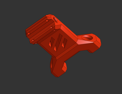
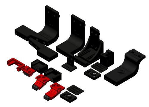
Klicky Probe for v2.4, v1.8, Trident, and Legacy
Microswitch probe with magnetic attachment, primarily aimed at CoreXY 3d printers with a focus on the Voron printers, should work on other printers with the variable mount.
The objectives for this project are:
drop in replacement for Omron TL-Q5MC2 or PL-08N2 (you don't need to replace the toolhead) easier and faster to build than similar probe types does not require soldering fixed probe dock mount (for the printers that are suported), less variables to adjust be able to detect all the print surfaces be as close to the hotend tip as possible highly repeatable and accurate probes less temperature variations no melting of its parts cheap to build It can also be used with the new automatic Z calibration klipper plugin to effectively calculate the Z offset from the probe and from the Z endstop.
The inspiration for the Klicky Probe comes from the Annex magprobe and the Euclid probe, it uses some concepts from each of the projects.
There is no need for supports, recommended settings are 4 perimeters/top/bottom, 13% infill.
The probe dock is mounted on the gantry, allowing it to be used as a Z endstop if desired (I use it that way).
There are three gantry extrusion mounts possible:
one fixed to be used on the Voron V2.4 or V1.8 AB with MGN12 or MGN9
- one that has some variance for other toolheads
- one fixed sidemount dock to allow a purge/scrub bucket on the left side of the bed
The fixed gantry extrusion mounts have been confirmed to work on the Voron V2.4 and V1.8
The normal magnet installation is that the two magnets that attach to the microswitch are installed with the same polarity, the 3rd magnet should have the inverse polarity. There is however the possibility that the magnets will demagnetize over time due to the alternating magnetic fields thay may result in a slow but sure demagnetization of the magnets, the magnets are so strong that may take a long time to show the effects of demagnetization YMMV.
No soldering is necessary, the probe microswitch connectors are also press-fit on the magnets.
The AB mount wires are also connected with pressure from the magnets, you can use the probe magnets as a template to insert the AB mount magnets, it is easier that way to don't insert the magnets the wrong way.
You will not lose Y travel on any configuration in the tests that were done.
It is also recommended to glue the magnets in place, superglue is good.
You will need to add macros to Klipper to be able to dock and undock the probe as necessary to do the Endstop (if necessary) and Quad Gantry Level, it is in the Klipper Macro directory.
Probe BOM:
1x microswitch (the omron D2F-5 or D2F-5L (removing the lever) is recommended) 2x M2x10 self tapping 4x 6x3 magnets AB mount BOM:
3x 6x3 magnets Probe Dock:
1x 6x3 magnets 2x M3x20 Fixed Dock mount:
2x M3 threaded insert M3x5x4 2x M5x10 2x M5 t-nut or equivalent or
variable Dock mount:
10x M3 threaded insert M3x5x4 8x M3x8 2x M5x10 2x M5 t-nut or equivalent If you would like to check a possibly more uptodate repository, check here
The macro is based on a version provided by the user garrettwp on Discord, many thanks to him. I have tweaked it a lot. It is also originally based on the great Annex magnet dockable probe macros "#Originally developed by Mental, modified for better use on K-series printers by RyanG and Trails" and can be found here
Would also like to thank the Voron discord community and VoronDesign for all the work that was and still is being made to maintain the Voron ecosystem.
The probe accuracy output is something like this: probe accuracy results: maximum 6.430000, minimum 6.426250, range 0.003750, average 6.428750, median 6.428750, standard deviation 0.000791
There is now an arrow on the probe telling you where should the switch pole be to have the correct offset. The probe offsets are:
z_offset = 6.42 x_offset: 0 y_offset: 19.75 Assembled Klicky Probe
Dock and undock video
It is working very well, if you decide to use it, give me feedback, either here, or on discord, my discord user is JosAr#0517.
By standing on the shoulders of giants, let's see if we can see further.
6,344 downloads
(1 review)0 comments
Updated
-
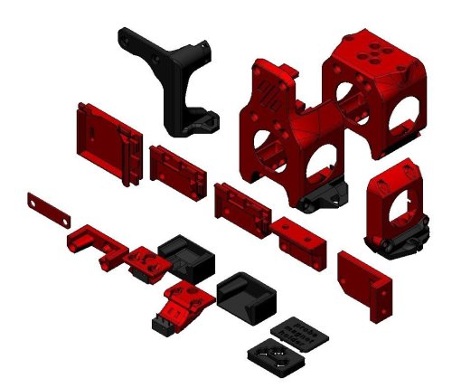
Klicky Probe for v0 Printers
This is an intermediate/advanced configuration, it's recommended to first build your Voron to the stock configuration
That way, you will be better familiarized with the concepts that are presented here and will have a much more enjoyable experience.
With an integrated mount, the bed can be fully used during printing, the bed only cannot be probed (at most) 6mm on the left side, this is due to the design of the probe, that extends below the nozzle.
There are currently two other probes available to use on the V0.1, Slideswipe and Sideswipe.
Above all, have fun and be excellent to one another, the instructions on how to install and setup the klicky probe for Vorondesign V0(.1) can be found [here](https://github.com/jlas1/Klicky-Probe/tree/main/Printers/Voron/v0), or below on this download
For me, and for a lot of users, it is working very well, if you decide to use it, give me feedback, either here, or on discord, my discord user is JosAr#0517.
By standing on the shoulders of giants, let's see if we can see further.
Mounting options
Probe dock mount
The probe dock is mounted to the front right extrusion, where it minimizes the chance of being removed inadvertently during printing, like this:
There are several mounting options, depending on your setup:
It can be frustrating on the v0 to add extra m3 nuts on the 1515 extrusion after the assembly is complete, so there are several screwless probe dock options to avoid that scenario.
Screwless variable Fixed Fixed extrabeef Top screws Side screws recommended for most setups, does not require extra m3 nuts on the extrusion (v0.0/1) fixed position, does not require extra m3 nuts on the extrusion (v0.1) fixed, fits X carriages that are 2mm thicker, does not require extra m3 nuts on the extrusion(v0.1) fixed, requires 2 extra m3 nuts on the top extrusion (v0.1) fixed, requires 2 extra m3 nuts on the front extrusion (v0.1) There are also some more mounting options on Usermods, like a servo powered dock. Check it out
Probe toolhead mount
The v0 toolhead was not designed to use a probe, so there is no inbuilt location to add one, so i designed two options for the v0.1 variant and one for the original v0.
Front cowling mount (v0.1)
You can install a mount the attaches to the front of the toolhead cowling, it will need 2/3mm of X space on the front right of the bed to avoid picking the probe up by accident, it is very easy to install, it's ideal to test the concept of probing on the v0.1
You will require 2x M3 x 40mm (BHSC preferably) that are not on the V0(.1) BOM, there is an included wire path with zip tie support, to keep your printer looking good.
Integrated cowling (v0.1)
You can replace the cowling with a version that has a cutout to allow the klicky mount to attach, it has no impact on the cooling performance of the probe, it also includes a wire path to the back of the miniAB.
This method allow mounting of different probes on the V0.1, currently only klicky uses this mount, hopefully that can change in the future.
It also allows to pick up the probe at X121, effectively outside the bed, incurring in a no print space lost.
Fan duct mount (v0.0)
On the V0.0, you do not need to reprint the entire cowlink, you only need to replace the right fan duct with a version that has a mount for klicky, it has no impact on the cooling performance of the probe, it also includes a wire path to the back of the miniAB.
This version has seen little tests because of the lack of a sufficient number of v0.0 to test on.
If you end up using this version, please tell me at what X do you dock and attach the probe.
It is also necessary to use the Screwless variable dock mount
Bill of Materials (BOM)
Tools:
1.5mm Drill (optional) Multimeter to check for Continuity Super Glue (optional) Soldering Iron Probe:
1x microswitch (the omron D2F-5 or D2F-5L (removing the lever is required), other also work with reduced accuracy or repeatability (mostly anecdotal evidence, needs a proper sudy) 2x M2x10 mm self tapping 10cm of 22AWG cable (to wire the magnets to the switch) 5x 6 mm x 3 mm magnets (N35 magnets work) Probe mount:
Front cowling mount (v0.1) Integrated cowling mount (v0.1) Fan duct mount (v0.0) 4x 6 mm x 3 mm magnets (N35 magnets work) 4x 6 mm x 3 mm magnets (N35 magnets work) 4x 6 mm x 3 mm magnets (N35 magnets work) 2x 20cm 22AWG cable (to connect the Klicky Probe to the umbilical termination point) 2x 20cm 22AWG cable (to connect the Klicky Probe to the umbilical termination point) 2x 20cm 22AWG cable (to connect the Klicky Probe to the umbilical termination point) two wires to connect the controller to the extruder motor vicinity two wires to connect the controller to the extruder motor vicinity two wires to connect the controller to the extruder motor vicinity 2x M3 x 40mm BHSC 1x M3x6 mm BHSC Screw 1x M3x6 mm BHSC Screw 1x M3 threaded insert M3x5 mmx4 mm 2x M3 threaded insert M3x5 mmx4 mm Probe dock:
1x 6 mm x 3 mm magnets (N35 magnets work) 2x M3x16 mm Probe dock mounts:
Screwless variable (v0.0/1) Fixed (v0.1) Fixed extrabeef (v0.1) Top screws (v0.1) Side screws (v0.1) 2x m3 nut 2x M3 threaded insert M3x5 mmx4 mm 2x M3 threaded insert M3x5 mmx4 mm 2x M3 threaded insert M3x5 mmx4 mm 2x M3 threaded insert M3x5 mmx4 mm 2x m3x8 mm 2x m3x8 mm Sourcing
To get the best experience, please consider purchasing from the trusted list of suppliers bellow.
trusted suppliers list
Parts location
The probe STL's are located here.
The printer specific STL's are located here.
The CAD with all the parts are here.
What to print
Probe
2x KlickyProbe_Long_v2.stl (keeping a spare is always a good idea) The KlickyProbe_v2.stl is also compatible, but has a different Y offset and cannot probe all the bed.
Helpers to pressfit the probe magnet
Probe_magnet_pressfit_helper.stl
Probe_magnet_holder.stl
Longer_probe_pressfit_helper.stl
Probe mount
Front cowling mount (v0.1) Integrated cowling mount (v0.1) Fan duct mount (v0.0) Front_cowling_mount.stl MiniAB_Dragon_Cowling_wKlicky.stl V0_Fan_duct_wKlicky.stl v0.1_integrated_mount.stl v0.1_integrated_mount.stl v0_integrated_mount.stl There are also other integrated cowlings, check the [STL] folder, namely, the Serpa_Mini_Dragon_Cowling_wKlicky.stl from Kyrios and the LGX Lite cowling from Bondtech.
Probe dock
Probe_Dock_v2.stl Probe dock mounts
Screwless variable (v0.0/1) Fixed (v0.1) Fixed extrabeef (v0.1) Top screws (v0.1) Side screws (v0.1) DockMount_variable.stl DockMount_fixed.stl DockMount_extrabeef.stl DockMount_TopScrews.stl DockMount_SideScrews.stl Printing instructions
Recommended printing settings:
initial layer height:0,24 layer height: 0.2mm bottom/top/perimeters: 4 infill: more than 23% infill type: Cubic Thin walls: On It was tested and printed with ABS, might work on other materials, if you try, let me know how it worked out.
Typical V0.1 components
(the images with the green background were provided by user SunB#1489 and are being used with permission).
Assembly
Step 1 - Dock mount and Probe Dock assembly
In this examples, the Fixed dock will be used.
2x M3 threaded insert M3x5 mmx 4 mm 1x 6 mm x 3 mm magnets 2x M3x16 mm Super Glue Here we will use the Fixed dock as an example, the other docks are very similar.
Install your heat set threaded inserts like you did within your Voron build.
Install the magnet in the Probe dock, make sure that the magnet is fully inserted, it's top should be below the plastic.
Screw the dock onto the Dock mount with the two M3x16mm screws.
Secure the magnet with a dab of super glue (not a lot, just a drop).
Mount the Probe Dock to the front right extrusion, snap first on the front extrusion, then on the top one (do this after assembling the probe).
Step 2: Probe Assembly
For the probe assembly you need the following parts:
1x microswitch 2x M2x10 mm self tapping 5x 6 mm x 3 mm magnets 10cm of 22AWG cable 1.5mm Drill (optional) Multimeter to check for Continuity Super Glue
Maybe you need to clear the holes for the microswitch, a 1.5mm drill bit should work fine.
Install the microswitch so that the arrow on the probe body is pointing to the little switch.
The best way to install the back magnet is to attach a magnet to the probe dock and slide the probe on the dock to insert some distance and the insert he remaining with a tool, it should be slightly below the plastic.
Then take your self tapping screws and screw the microswitch in place, you should also now solder the wires to the outside pins of the switch, that way making this a Normally Connected probe.
You should place the wires cover outside the ducts to the magnets and install them in the space below the magnets, more like the right wire is on the image below.
You want to install the magnets in the way that the ones which are connected to the microswitch, have the same polarity.
Before placing the switch magnets, use some super glue on the holes (not a lot, just a drop), avoid the wires and the top of the magnets.
The 3rd magnets (there are two) should have the inverse polarity, wait until the system is complete and assembled before gluing the magnets, they might need adjustment to ensure a good fit on the mount.
You can use the included pressfit helpers to help in securing the probe when you are inserting the magnets.
There is no need for soldering, the probe microswitch connectors are press-fit on the magnets, they should remain with the top above the probe plastic.
As the last step of the probe assembly check if you have continuity between two magnets that connect to the switch.
If you have a normally closed switch (as you should), then you should have a current flow, so continuity is established. When you press the switch you should lose continuity. When you have a normally open switch then the behavior is the other way around.
Step 3: Probe mount Assembly
In this example, the Front cowling mount will be used.
For the Front cowling mount assembly you need the following parts
4x 6 mm x 3 mm magnets 2 x 20cm 22AWG cable to connect the Klicky Probe to the Mircofit Terminal two wires to connect the controller to the extruder motor vicinity some microfit or JST hardware 2x M3 x 40mm BHSC Multimeter to check for Continuity Super Glue The probe mount wires are also connected with pressure from the magnets, you can use the probe magnets as a template to insert the probe mount magnets, it is easier that way, so that the magnets are not inserted the wrong way.
again, before placing the wire magnets, use some super glue on the holes (not a lot, just a drop), avoid the wires and the top of the magnets.
The 3rd magnets (there are two) should have the inverse polarity, exacly like on the probe.
Wait until the system is complete and assembled before gluing the 3rd magnets, they might need adjustment to ensure a good fit on the probe.
(The mount has since been improved a bit to avoid cracking)
After everything is assembled let's check again for continuity, this time joining the ends of the cable and testing connectivity on the two wire magnets that have a cable.
Step 4: Probe Mount installation and wiring
For the installation you need the following parts:
2x M3x40 mm BHSC Screws
Route the probe mount cables to near the end of the V0 umbilical, install a male terminal in there.
Before going further, please turn off the printer, the SKR boards are very picky with short circuits.
Connect a female terminal to the wires that will run in the umbilical from the toolhead to the controller.
Connect the wires from the Klicky Probe to the Zprobe port, on GND and PC14 bin (I reused the LDO kit connector)
When testing the docking and attachment of the probe, make sure that the back magnet of the probe and the dock magnet do not touch, if they do, it will make attaching the probe much harder.
Step 5: klipper configuration
Unfortunately, I do not know how to document RRF probe configuration, so here is only Klipper configurations.
As of right now, klipper and RRF have no inbuilt support for a removable probe, fortunately, it does support very robust macro programming, so you will need to add macros to be able to dock and attach the probe as necessary, as well as supporting the rest of the functions that require the usage of a probe.
The macros and instructions on how to configure are located on the Macro directory, you need to check that before continuing on the build, there are also some RRF scripts that work for the Voron V2.4.
For the Voron v0, these are the recommended configuration on the klicky-variables.cfg:
variable_verbose: True # Enable verbose output variable_travel_speed: 100 # how fast all other travel moves will be performed when running these macros variable_dock_speed: 50 # how fast should the toolhead move when docking the probe for the final movement variable_release_speed: 55 # how fast should the toolhead move to release the hold of the magnets after docking variable_z_drop_speed: 20 # how fast the z will lower when moving to the z location to clear the probe variable_safe_z: 25 # Minimum Z for attach/dock and homing functions # if true it will move the bed away from the nozzle when Z is not homed variable_enable_z_hop: True # True v0 #Dock move Variable_dockmove_x: 0 # Final toolhead movement to release Variable_dockmove_y: 40 # the probe on the dock Variable_dockmove_z: 0 # (can be negative) #Attach move Variable_attachmove_x: 30 # Final toolhead movement to Dock Variable_attachmove_y: 0 # the probe on the dock Variable_attachmove_z: 0 # (can be negative) variable_max_bed_x: 120 # maximum Bed size avoids doing a probe_accuracy outside the bed variable_max_bed_y: 120 # maximum Bed size avoids doing a probe_accuracy outside the bed
The sections below should be added to klicky-specific.cfg, that way, it will be loaded on klipper via a klicky-probe.cfg include.
If you would like to use a bed mesh, this is the recommended settings:
[bed_mesh] mesh_min: 15,15 mesh_max: 105,105 speed: 100 horizontal_move_z: 20 probe_count: 3,3 #if you would like more detail, use 5,5 here relative_reference_index: 4 #if you use 5,5 above, place 12 here move_check_distance: 3 algorithm: lagrange fade_start: 1 fade_end: 10 fade_target: 0 split_delta_z: 0.0125 mesh_pps: 2,2
Regarding the Screws Tilt Adjust (Klipper probes the three screws positions and recommends the number of turns to level the bed), you can use this configuration as a reference, the probe should be over the screws when you do send the nozzle to the respective coordinate:
[screws_tilt_adjust] screw1: 100,115 #For Long probe screw1_name: back right screw2: 0,115 #For Long probe screw2_name: back left screw3: 60,5 #For Long probe screw3_name: front screw horizontal_move_z: 20 speed: 100 screw_thread: CW-M3
You should test this and adjust accordingly.
This is probe configuration is with the default Voron v0.1 SKR mini E3 v2 configuration, with the probe connected to the PC14 pin, please update it to your specific configuration:
[probe] #with Long Klicky Probe pin: ^PC14 x_offset: 8 #(9.5 with front cowling) y_offset: 0 z_offset: 14.5 speed: 7 lift_speed: 7 samples: 3 samples_result: median sample_retract_dist: 2 samples_tolerance: 0.01 samples_tolerance_retries: 10
I recommend a probing speed between 5mm/s and 10mm/s, you may experiment to see what is the better speed for your machine. Please confirm that if you are not using a endstop pin, that the pull-up is enable by using the ^ sign, normally the endstop pins have a hardware solution that does not require this configuration. Depending on your switch you may need to add a ! to invert that pin (normally open vs. normally closed).
Z endstop and Probe configuration
If you want to use the Klicky Probe as your Z endstop, you need to change the endstop_pin: under the [stepper_z] section to probe:z_virtual_endstop.
Just comment out the old one and add a new line endstop_pin: probe:z_virtual_endstop.
You will need to update the Z probing variables, set the two variables below to 0, it will probe the middle of the bed.
variable_z_endstop_x: 0 variable_z_endstop_y: 0
Assembled Klicky Probe
Step 6: klipper Dock/Undock configuration
X max position adjustment
Even in the stock X endstop with a lever, you normally can add a extra mm of X travel due to the lever extra trigger distance:
[stepper_x] position_endstop: 120 position_max: 121 Adjust Probe Pickup Position
One of the last things we need to do is to adjust the probe pickup position.
Make sure that the x and y axis are homed and the probe is manually attached to mount.
Now manually (with gcode commands) move the toolhead to the probe dock and move it so far to the back that the probe docks, note the Y-Position.
Next, again manually, move the toolhead parallel to the probe dock until the probe it is perfectly aligned with the mount, note the X.Position.
Open your klicky-variables.cfg and find the #dock location section and edit the following two line
variable_docklocation_x: variable_docklocation_y: Test now with the ATTACH_PROBE and DOCK_PROBE if it docks and is removed correctly, some common points that can give problems are:
the dock magnet is touching the back probe magnet, they cannot touch, push them further in the probe is hitting the dock arms, please move the toolhead more to the side where the probe does not hit, by 1mm at a time, until it works the probe is falling after being release, the dock is too far away, you can insert one or several 1mm spacer to move the dock and solve this WARNING when you are doing PROBE_ACCURACY, make sure that the probe is above the bed, the PROBE_ACCURACY macro does not move the toolhead in X or Y.
Congratulations, your done :).
Firsts tests
Before starting to test klicky, and from past mistakes, please remove your PEI sheet (the probe works on the magnetic sheet) and if possible, change your printer maximum speed, acceleration and Z current, on klipper with TMC steppers, you can do this:
SET_TMC_CURRENT STEPPER=stepper_z CURRENT=0.2 SET_VELOCITY_LIMIT ACCEL=1000 SET_VELOCITY_LIMIT VELOCITY=50 Enjoy your Klicky Probe!
Dock and undock video
It is working very well, if you decide to use it, give me feedback, either here, or on discord, my discord user is JosAr#0517.
By standing on the shoulders of giants, lets see if we can see further.
2,347 downloads
(0 reviews)0 comments
Updated
-
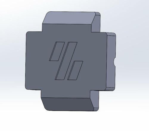
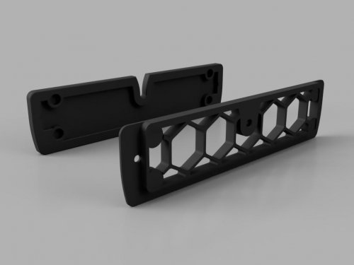
Magnetic Grill Cover
Magnetic Exhaust Grill Cover
Depending on my printer location and / or cooling needs, I sometimes want the exhaust vent shut off to just rely on recirculated filtering with a nevermore or similar. This mod replaces the default exhaust grill with one featuring magnets and a captive path for the bowden tube. There is then a magnetic cover that will fit around the bowden and seal the grill. It's intended to be installed with the exhaust as normal, but should also be able to attach without by using a couple of M3 nuts and the default [a]_exhaust_filter_mount_x2.stl mounts.
BOM
8x 6x3mm round magnets (Voron BOM spec) 50cm foam tape 1mm thick, 5mm wide. It was designed for this tape but you can probably get away with varying both thickness and width depending on magnet strength, or even leaving it out if your print is flat enough to seal and you don't mind magnets going clack against each other. 2x M3 Nuts (optional) Installation
Insert magnets into outer four pockets on each piece. They should be push fit, but a dab of superglue wouldn't hurt. Test fit the bowden tube on the middle grill hole. The part is designed to be particularly tight around the tube, and ideally you'd clear the hole with a 4mm bit to get it nice and snug to the tube. Stick the foam tape around the outside rim of the cover. It doesn't matter if you do this in multiple pieces (as there are some awkward turns). Just try to get it flat and continuous to aid the seal. Install exhaust grill as normal / using M3 nuts Feed the bowden tube through the centre hole
Notes
As previously mentioned, the bowden hole is intended to be tight to the tube. You can either drill it for perfection, or adjust the size in the CAD using parameters in Fusion. If you have other magnets then you can also tweak the parameters in Fusion for these (to an extent). If you don't want to lose the cover, you can hang it from the bottom pair of magnets. You lose a bit of ventilation doing so, but it's one less bit of clutter. Thanks
Many thanks to Lanman1 for being a guinea pig for this and giving feedback!
135 downloads
(0 reviews)0 comments
Updated
-
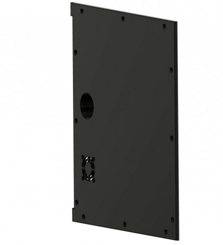
Side Panels
Side panels with integrated hinge.
Carefully drill the 1mm hole to 2.5mm and cut an M3 thread into it
Required material:
2x M3x30 BHCS
1x 30x30x10 5V Fan for Raspberry Pi cooling
1x https://www.amazon.com/ZHSMS-Universal-Replacement-Motorcycle-Waterproof/dp/B08L33RFHY/
1x https://www.amazon.com/Angled-USB3-0-Extension-Industrial-Computer/dp/B07LBFPG16/
0 downloads
(0 reviews)0 comments
Updated
-
ESP32 DIN Rail Bracket
This is a DIN rail bracket for an ESP32 bought from AZ-Delivery via Amazon
May also fit for other ESP32 dev boards, but I have not tested. The spacing for the bores is: 23mm x 51mm
Please use the generic PCB DIN Clip and mount these on top.
27 downloads
(0 reviews)0 comments
Updated
-
V01 Motor Panel No Rub
Voron v0.1
What is this?
This modification keeps the umbilical and reverse bowden tube from rubbing against the motor belts.
How do I use it?
Replaces the Motor Panel and reuse the same M3x8 screws
How should I print this?
Same as any other Voron part. Printed with Polylite ASA
56 downloads
(1 review)0 comments
Updated
-
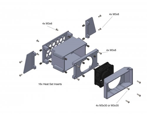
Tophat Exhaust Filter
After growing tired of my room smelling of ABS, I decided to create an exhaust and filter system that could be printed entirely on a v0. This mod utilizes 5 layers of 10mm thick activated charcoal sheets, a 60mm x 25mm fan and an optional Roomba HEPA filter. I have tested it throughly and my design almost entirely eliminates the ABS smell during and after printing.
The entire assembly (With the HEPA filter attachment) sticks out about 110 mm past the rear of the printer.
BOM
4x M3x6 screws 8x M3x6 or M3x10 screws 4x M3x30 or M3x35 screws 16x Heat set inserts 10mm Activated Charcoal sheets Link 24v 60mm x 25mm fan Link OPTIONAL Roomba HEPA filter Link Assembly
Before printing the Fan_Cover make sure to check where the wires from your fan exit the housing and select the corresponding stl. The fan wires snake through the assembly and exit through one of the holes in the grill. You will also need to cut 5 55mm x 90mm sheets of activated charcoal to fit into the chamber
Wiring and Klipper
If you're using an SKR mini v1.2 then you must move the hotend fan from pin FAN0 to FAN1. This allows the exhaust fan to be controlled via PWM instead of the hotend fan since the 1.2 board only has 1 controllable fan port. If you're using the v2 then you don't have to worry about that step because both fan ports are controllable.
Add this to your config assuming the exhaust fan is plugged into FAN0 (PA8)
[fan_generic exhaust_fan] # Exhaust Fan pin: PA8 max_power: 1.0 shutdown_speed: 0 kick_start_time: 0.5 You can then control the fan speed with
SET_FAN_SPEED fan=exhaust_fan SPEED="number between 0 and 1" For example, to put the fan speed at 30% use,
SET_FAN_SPEED fan=exhaust_fan SPEED=0.3 Running the fan at 30% speed during a print has lead to a dramatic decrease in ABS fumes and pretty much made them unnoticeable. I also run the fan at 100% speed at the end of a print to fully exhaust the print chamber. Adding foam tape to seal up any gaps between panels and the top-hat will also greatly increase the reduction of fumes.
236 downloads
(0 reviews)0 comments
Updated
-
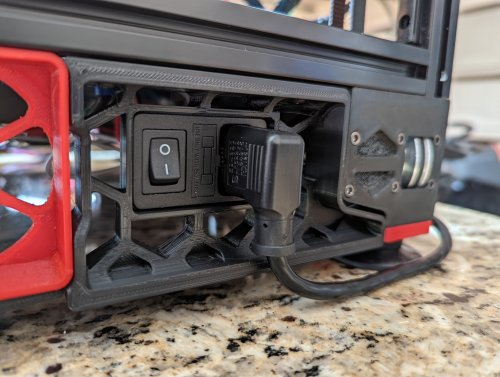
350mm Side Skirt_for Generic Power Plug v2.4 r1
Right rear side b for a Voron 2.4 r1 350 with generic power plug.
43 downloads
(0 reviews)0 comments
Updated
-
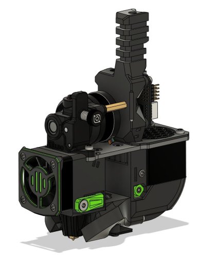
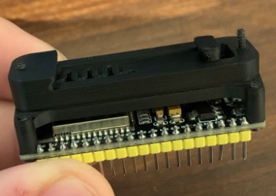
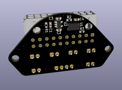
Voron-0 Umbilical PLUS (with integrated ADXL345)
The Voron-0 Umbilical is a well known and very useful addition to your 3D Printer, originally created by GitHub user timmit99 and can be found in the official Voron-Hardware repository here.
In this new 'Plus' version, I have added a permanent ADXL345 Accelerometer to the Toolhead board, to make input shaper tuning (and possibly other interesting use-cases) more accessible to users. The Molex MicroFit connector was changed from a 14-pin to 20-pin version to acommodate the additional wires for the ADXL345.
The Toolhead PCB can be ordered pre-assembled from JLCPCB (using the included CPL and BOM file) so you do not have to solder the delicate electronics yourself, just the connectors (as you need to do with the original V0-Umbilical).
You can find a full README and Photos/CAD/Design data at my github repository: https://github.com/skuep/V0-Umbilical-Plus
Frame PCB BOM
Part Quantity Notes LCSC Part Number Link 20 Pin Socket 1 MOLEX 430452012 C485575 https://www.lcsc.com/product-detail/Wire-To-Board-Wire-To-Wire-Connector_MOLEX-430452012_C485575.html SMD Thermistor 1 100K 0805 Thermistor C143680 https://lcsc.com/product-detail/NTC-Thermistors_Vishay-Intertech-NTCS0805E3104FXT_C143680.html 2 pin JST XH 5 2.5mm pitch C158012 https://lcsc.com/product-detail/Wire-To-Board-Wire-To-Wire-Connector_JST-Sales-America-B2B-XH-A-LF-SN_C158012.html 3 pin JST XH 2 2.5mm pitch C144394 https://lcsc.com/product-detail/Wire-To-Board-Wire-To-Wire-Connector_JST-Sales-America-B3B-XH-A-LF-SN_C144394.html 4 pin JST XH 3 2.5mm pitch C144395 https://lcsc.com/product-detail/Wire-To-Board-Wire-To-Wire-Connector_JST-Sales-America-B4B-XH-A-LF-SN_C144395.html 6 pin JST XH 1 2.5mm pitch C144397 https://www.lcsc.com/product-detail/Wire-To-Board-Wire-To-Wire-Connector_JST-Sales-America_B6B-XH-A-LF-SN_JST-Sales-America-B6B-XH-A-LF-SN_C144397.html Screw Terminal 1 5.08mm pitch C8465 https://lcsc.com/product-detail/Screw-terminal_Ningbo-Kangnex-Elec-WJ500V-5-08-2P_C8465.html Optional Parts
Part Quantity Notes LCSC Part Number Link 0805 10uF Capacitor 3 Use if using BARE neopixel IC's. Strips have these already. C17024 https://lcsc.com/product-detail/Multilayer-Ceramic-Capacitors-MLCC-SMD-SMT_Samsung-Electro-Mechanics-CL21A106KPFNNNE_C17024.html Toolhead PCB BOM
Part Quantity Notes LCSC Part Number Link 20 Pin Socket (Right Angle) 1 Molex 430452000 C485576 https://www.lcsc.com/product-detail/Wire-To-Board-Wire-To-Wire-Connector_MOLEX-430452000_C485576.html 2 pin JST XH 6 B2B-XH C158012 https://lcsc.com/product-detail/Wire-To-Board-Wire-To-Wire-Connector_JST-Sales-America-B2B-XH-A-LF-SN_C158012.html 4 pin JST XH 1 B4B-XH C144395 https://lcsc.com/product-detail/Wire-To-Board-Wire-To-Wire-Connector_JST-Sales-America-B4B-XH-A-LF-SN_C144395.html LP2985-33DBVR 1 3.3V LDO C95414 https://www.lcsc.com/product-detail/Linear-Voltage-Regulators-LDO_Texas-Instruments-LP2985-33DBVR_C95414.html ADXL345BCCZ 1 Accelerometer C9667 https://www.lcsc.com/product-detail/Motion-Sensors-Accelerometers_Analog-Devices-ADXL345BCCZ-RL7_C9667.html 10 Ohm Resistor 2 0603 size C22859 https://www.lcsc.com/product-detail/Chip-Resistor-Surface-Mount_UNI-ROYAL-Uniroyal-Elec-0603WAF100JT5E_C22859.html 10 kOhm Resistor 1 0603 size C25804 https://www.lcsc.com/product-detail/Chip-Resistor-Surface-Mount_UNI-ROYAL-Uniroyal-Elec-0603WAF1002T5E_C25804.html 4.7uF Capacitor 2 0603 size C19666 https://www.lcsc.com/product-detail/Multilayer-Ceramic-Capacitors-MLCC-SMD-SMT_Samsung-Electro-Mechanics-CL10A475KO8NNNC_C19666.html 10nF Capacitor 2 0603 size C57112 https://lcsc.com/product-detail/Multilayer-Ceramic-Capacitors-MLCC-SMD-SMT_10nF-103-10-50V_C57112.html/?href=jlc-SMT Corresponding CPL and BOM files are included in the repository. Using these files you can easily get yourself a ready-made assembled PCB from JLCPCB so you don't have to have the skills to solder the fine-pitch and 0603 packages.
Umbilical cable
The Umbilical cable is a 220-240mm dual ended 20P (2x10) microfit cable. The connectors are wired 1:1 so pin 1 connects to pin 1 and so forth for all 20 pins.
Cable BOM
Part Quantity Notes LCSC Part Number Link 20 Pin Plug 2 Molex 430252000 C485324 https://lcsc.com/product-detail/Connectors-Housings_MOLEX-430252000_C485324.html Crimps 20 AWG 12 Molex 430300001/430300007 C259786 https://lcsc.com/product-detail/Line-Pressing-Terminals_MOLEX-430300001_C259786.html Crimps 26 AWG 28 Molex 430300004/430300010 C259765 https://lcsc.com/product-detail/Line-Pressing-Terminals_MOLEX-430300004_C259765.html 20AWG Wire 12 220mm Sections PTFE/Silicone/Hefulon for motion rated, PVC could work since it isn't constraind to a cable chain 26AWG Wire 28 MicroFit connectors support two different ranges of conductor thickness using different wire crimp ferrules. I recommend that you realize the stepper motor and heater wires with 20AWG wire (0.5mm²) and the remaining wires in 26AWG wire (0.14mm²) to save on weight and accelerated mass.
Hints and Remarks
Extruder Stepper Direction
The umbilical cable reverses the stepper rotation direction. I.e. you need to invert the DIR pin of the extruder motor in your printer.cfg file.
[extruder] .... dir_pin: PB4 # Add ! (or remove ! if already there) before 'PB4' ....
Mounting the Toolhead PCB
The umbilical toolhead PCB uses heat stake inserts in order to mount it to the motor screws. In some cases (i.e. LDO motors), the extruder motor already has an additional thread, which has to be either removed by drilling the motor holes with a 3mm spiral drill. If you do not want to drill into the motor, you can use M3x10 captive screws, which are unfortunately hard to find. These screws have a narrowed section and a short thread at the tip so they only 'grab' the thread of the heat stake inserts.
Additional chamber thermistor on SKR mini V2.0
If you are using the SKR mini V2.0 board and you want to connect the chamber thermistor, you can use Timmit99's expansion board (https://github.com/VoronDesign/Voron-Hardware/tree/master/SKR-Mini_TFT_Thermistor_Board).
If you want an easier and faster solution, you can move the Z-STOP endswitch pin and connect it the E0-STOP pin using a simple self-made JST 2-pin to 3-pin adapter (See Photos folder) or by removing the crimp pins from the 2-pin JST and insert them into the housing of a 3-pin JST header. Once the Z-STOP pin is freed up, you can use it for your thermistor. This method needs the following printer.cfg changes:
[stepper_z] ... endstop_pin: ^PC15 # Conversion for additional thermistor (use E0-STOP for Z-STOP) ... [temperature_sensor chamber] sensor_type: Generic 3950 sensor_pin: PC2 gcode_id: C pullup_resistor: 10000
Connecting the ADXL345 to a Raspberry Pi
The ADXL345 circuit on the toolhead PCB includes a R-C filter and a 3.3V low-dropout regulator to deliver a clean power supply. Thus you can use the official drawings shown in the corresponding docs (https://www.klipper3d.org/Measuring_Resonances.html), with one small change. You need to connect VCC to +5V (Pin 2 or Pin 4) instead of 3.3V (Pin 1) on the Raspberry Pi extension header (See Photos folder). Then follow the official docs for setting the resonance measurement up.
191 downloads
(0 reviews)0 comments
Updated
-
V0.1 - Mini Afterburner ADXL345 Mount
This is a modified version of the strain relief for the mini AB, which provides a well-hidden permanent mount for a cheap Chinese ADXL345 module.
You need 2x 4mm heat inserts as well as 2x M3 6mm screws to attach it.
67 downloads
(0 reviews)0 comments
Submitted
-
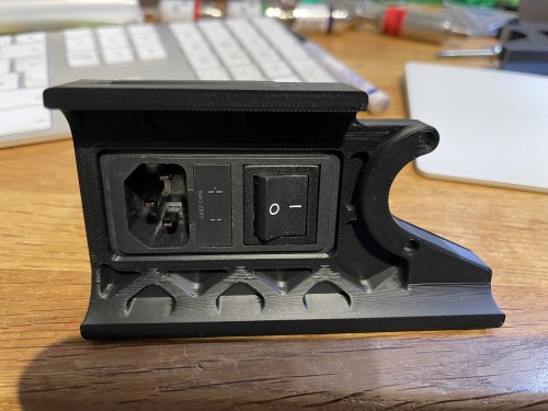
Schaffner FN-286-10-06 plug panel for 2.4r2
I love the Schaffner power inlet - highest quality, and much more safe than other cheap Chinese ones.
So I made a quick mod for my next 2.4r2 build.
Hope you like it
14 downloads
-
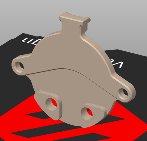
CRTouch Snap Mount
Voron 2.4 CR Touch Snap Mount (Beta)
Drop-in Probe Replacement for v2.4 Using Single or Double MGN9 Rail(s).
Stealthburner Compatible but Will NOT Fit on MGN12 (Trident or V2.4r2)!
I've been looking for simpler alternatives to the common probe mods that is also compatible with the standard MGN9 mount. This requires no modification to the printer and uses existing mounting holes and routing. It does require part of the probe's shell be trimmed and must only be powered by 5V!
The big question is, are these even reliable on a Voron? Well, it is well known that BL Touch probes have issues with heat in closed chambers but the CR Touch photoelectric sensor and metal pin design seem to be better suited for this. I'm currently testing reliability but so far have had no significant issues inside an enclosure with temperatures ranging from ~45-60C. Creality lists a max operating temp of 65C but I haven't found much more information. I'm now testing on my v2.4 and will update with any issues.
I'd appreciate feedback from anyone who has used a CR Touch on their Voron or would like to help test. I suggest newer builders stay with the standard options or the well-tested clicky mod.
Finalized CAD files will be posted after beta.
BOM
Size Qty Creality CR Touch 1 M3x8 or M3x10 BHCS/SHCS 2 M3x5 Heat-Set Insert 2
Rear Spacer is Optional
Instructions
With the wiring detached, carefully seperate the 2 shell pieces by gently pressing the 2 clips on each side. Only the probe side will be used. Be very careful not to break the clips off.
Cut off the top mounting tabs so nothing extends past the sides of the shell. I used a dremel finished off by a file in about 5 min. Careful not to damage the components and blow off any debris build up, especially near the sensor.
Press two M3 heat-set inserts into the printed mount then snap the shells together. Make sure all snaps are secured. Tolerances are intentionally tight. If multiple tabs are broken, a strip of electrical tape can be used.
Slide in the probe then attach it from the back with two M3x8 screws (M3x10 recommended with alignment spacer). Longer screws could be used but be careful not to hit the PCB.
Examples shown are on a single MGN9 rail mod
Please contact [email protected] to report issues or suggestions.
113 downloads
-
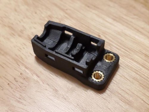
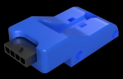
Ab Plug Microfit 1x4
Voron 2.4 AB Plug (Microfit 1x4)
This mod is to add a plug to the gantry to connect the A
132 downloads
.thumb.jpg.1e67bb19045c04050d6d61c111a85fd2.jpg)
-
Most Actively Discussed Mods
-
Hottest Files!
.thumb.jpg.2c879d60315f8d86612bb06a137c204a.jpg)