-
TeamFDM.com is an UNOFFICIAL companion site for the DIY Voron 3D printer community. For official docs and final source of truth, visit the Official Voron Discord or the Voron Github
Printable Voron User Mods
Voron User Mods, or "UserMods", are a collection of community created and Team FDM curated modification for Voron Printers. All of these mods are available on the VoronUsers Github repo and unless otherwise specified follow the Voron communities GPL3.0 Licensing. Use any Mods at your own risk, if you make modification please share them on the VoronUsers repo.
Mod Authors: Have a Voron mod? Upload it at TeamFDM.com and let us know you're the author. We will ensure you can update and curate your files for more feedback! Please include tags for what Voron, or extruder your mod is compatible with.
652 files
-

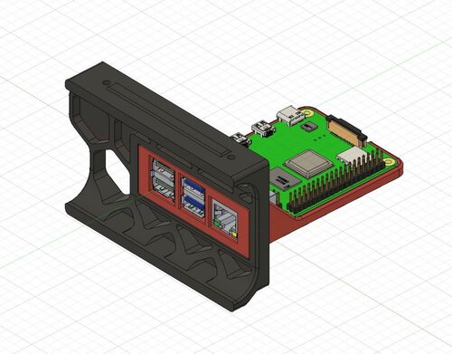
PiPlate
If you want to mount your Raspberry Pi so the usb and ethernet ports are externally accessable, look no further.
Supported: Pi 3B/4B and Trident or Voron 2.4 machines.
New Support added for Voron 2.4 250 size, and all 3 sizes of V2.4r2
BOM: Uses stock hardware, no additional parts required. M2 screws for Pi to plate, other hardware is the same as stock skirt installation.
1,038 downloads
- LoganFraser
- v2.4
- (and 1 more)
-
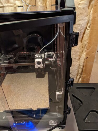
Clip On Door Frame
V2.4 Clip-On Door Frames
This design builds on Alexander-T-Moss 270 degree hinges by adding a clip-on frame around the front doors to provide better sealing and stiffining of the front door panels.
The clips consist of three types of components - angle_frame_1, angle_frame_2, and straight_frame. Each door will need a one of each angle_frames, with one on the top of the door and one on the bottom of the door. For the left door, angle_frame_1 goes on the bottom of the door and angle_frame_2 goes on top of the door. For the right door, angle_frame_1 goes on the top of the door and angle_frame_2 goes on the bottom or the door.
A long and short version of the straight_frame is provided depending on if you have two or three hinges installed on each door. If you have three hinges installed for each door, you will need to print out two short straight_frames for each door.
If you use the stock V2.4 magnetic door latch, extended_door_latch is provided which moves the frame magnets out closer to the handle magnets.
Important Notice
These are currently sized for the 300x300x300mm V2.4 build. If anyone is interested, I can make them for the 250 and 300mm sizes as well.
Kind-Of Important Notice
The parts are not symmetrical - there is a 'thick' side and a 'thin' side. The thin side goes towards the frame.
BOM
Printed Parts
angle_frame_1_x2.stl [x2] angle_frame_2_x2.stl [x1] straight_frame_short_x4.stl [x4] (If you use three hinges per door, x0 otherwise) straight_frame_long_x2.stl [x2] (If you use two hinges per door, x0 otherwise) extended_door_latch_x2.stl [x2] (If using the stock V2.4 door latch, x0 otherwise) Printing
I recommend following the default settings for Voron Parts, and none of the parts require support material.
Layer Height : 0.2 mm Extrusion Width : 0.4 mm Infill : 40 % Perimeters : 4 Solid Top/Bottom : 5 Supports : No Brim : Optional Assembly
Attach one angle_frame_1 to the bottom of the left door and one angle_frame_1 to the top of the right door. Attach one angle_frame_2 to the top of the left door and one angle_frame_2 to the bottom of the right door. If you have three door hinges installed, install two straight_frame_short sections to each door. If you have two door hinges installed, install one straight_frame_long section to each door. If you are using the stock V2.4 magnetic door latch, install the magnets into the extended_door_latch and replace the existing door latches with the extended version.
Installed On My 2.4
195 downloads
-
Z Locks
Z Locks
When installing the gantry into the frame, use Z Locks as helping hands to hold the gantry in place for later build steps. They hold the gantry in place even when flipping the printer and can take pressure on the gantry up or down.
There are three lengths, 100mm, 150mm and 200mm. The 150 length seems to be ideal during a 350 build, gives some room to still fit drivers above and below the gantry.
Gantry Install
Follow the typical steps in the build manual up to the Gantry Install section. Use the Z Locks instead of the long zip ties.
Place the printer on its back Position the gantry inside the frame Twist in the Z Locks, connecting the gantry to the top of the frame Use pliers to twist in, they're tight to prevent slipping when flipping the printer They do have a twist direction, note the position of the rounded corners Use five or six Z Locks The cable chain bridge will prevent movement along the Y axis if it hits a Z Lock. Something to consider while positioning a Z Lock on the right side of the gantry. Important - Do not forget to remove all Z Locks before printing!
Bonus Steps
After installing the Z Locks, do not stand up the printer yet. If the build manual was followed, the gantry has the Z belts attached. While the printer is still on its back, fish the Z belts through the Z drives. This is much easier with the printer on its back.
Enjoy!
428 downloads
(0 reviews)0 comments
Submitted
-
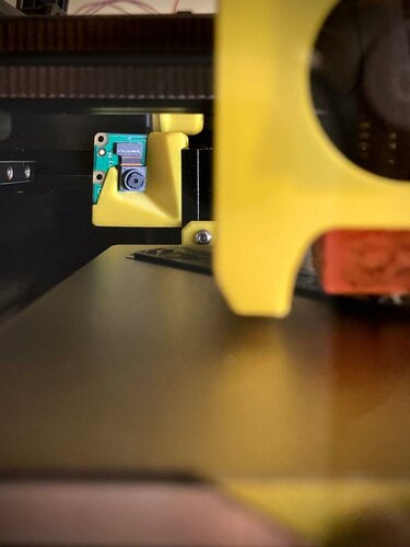
Raspberry Pi Camera Mount
Voron 0/0.1 Raspberry Pi Camera Mount
This is a low profile raspberry pi camera mount for the Voron 0 / Voron 0.1.
Please consider downloading this model on Printables as well to help me earn a roll of Prusament 😆
TLDR
Raspberry pi camera mount for the voron 0 / voron 0.1 Get up close and personal with the nozzle44 downloads
(0 reviews)0 comments
Submitted
-
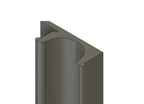
6mm Slot Cover
# Cover for extrusion with 6mm slot width
Two simple files. One is symmetric and can be used for slots that are inside the printer. One isn't symmetric and can be used on external frames, where there are clear panels.
562 downloads
-
Fannypack Zero
FANnypack Zero
This is a simple and yet overkill electronics cooling solution originally intended for the Voron Zero however could also be installed on any printer with a solid panel covering the electronics area.
Assembly
Linked products are an example, other brands work just fine! That said using the affiliate link helps support future developments and costs you nothing :)
BOM:
1x 8015 axial fan affiliate link / 8015 axial fan normal link 4x M3x20mm screw 4x M3 inserts 1x modified electronics back panel 1x printed fan cover use the dxf and a laser cutter at your local makerspace to produce the holes in the panel or print it out and use it as a template to do it manually. If enough people express interest Funnsor said they would stock some panels so drop me a message if you would want to buy in a whole new panel instead of modifying your old one.
Install m3 inserts in the printed fan cover
Poke wire through the hole and then attach fan and cover to the outside of the panel using the m3 screws.
Depending on your control board you may need to use a klipper expander affiliate link / klipper expander normal link board to gain an additional controllable fan output.
For info on wiring and detailed assembly pictures etc. please take a look at the guide I did here as part of a general upgrade to my V0.1
Feedback
Feel free to contact me - I'm Slzer#2881 on the discord.
30 downloads
(0 reviews)0 comments
Submitted
-
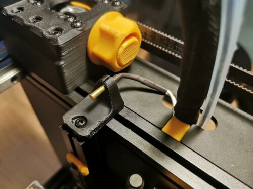
Thermistor Holder Zero
Thermistor Holder Zero
This is a really simple remix of the thermistor holder by samwiseg0. It increases the length of the flange to give clearance for the voron zero printhead and X axis. You can see a comparison of the original version vs my extended version.
Assembly
Linked products are an example, other brands work just fine! That said using the affiliate link helps support future developments and costs you nothing :)
BOM:
1x cartridge thermistor affiliate link / cartridge thermistor normal 1x M3x8mm screw 1x printed thermistor holder zero You may need to tap a m3 thread in the top end of the left hand vertical Z extrusion (aim for 10mm depth of thread). Once tapped bolt the printed thermistor holder on using the M3x8 screw. The thermistor can then be pushed into the holder and the wire poked through the hole into the electronics bay.
For info on wiring etc. please take a look at the guide I did here as part of a general upgrade to my V0.1
Feedback
Feel free to contact me - I'm Slzer#2881 on the discord.
87 downloads
(0 reviews)0 comments
Submitted
-
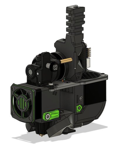
Voron2.4 Trident Pins Mod
This has been updated for V2.4r2 and Trident
This mod is for the V2/Trident, it involves printing new AB drive frames, new XY Joints, new Front Tensioners, and new Z idlers
The pins have replaced m5 screws, at any location where the screw acts like a shaft, holding bearings, pulleys or idlers. This allows for smoother rotation and stops the possibility of motion parts being caught in threads. This work was done by everyone, thanks to ABS plastic and voron printers for the fast iteration, @doomweasel? they fall out yet?
To complete this mod the following files will need to be reprinted
A and B drive units
a_drive_frame_lower_pinned.stl a_drive_frame_upper_pinned.stl b_drive_frame_lower_pinned.stl b_drive_frame_upper_pinned.stl Front Idlers
[a]_a_tensioner_pinned.stl [a]_b_tensioner_pinned.stl XY Joints
MGN12_xy_joint_left_upper_pinned.stl MGN12_xy_joint_left_lower_pinned.stl MGN12_xy_joint_right_upper_pinned.stl MGN12_xy_joint_right_lower_pinned.stl Z Idlers FOR V2 either one of these based on if you are using 6mm or 9mm belt
[a]_z_tensioner_x4_6mm_pinned.stl [a]_z_tensioner_x4_9mm_pinned.stl here is what the XY Joint will look like
here is what the Z idler will look like
the following 5mm Pin hardware is what is needed as well
BOM
[A-B] 30mm (x2) 28mm (x2) [X-Y Joints] 40mm (x4) [X-Y Idlers] 43mm (x2) [Z Idlers] 28mm (x4) these can be purchased from here
Smooth pins
https://www.aliexpress.com/item/1739093502.html
Misumi Part Numbers
Part NO. Qty SFR5-30 2 SFR5-43 2 SFR5-40 4 SFR5-28 6 The following users are the main contributors to this mod
@RoboDave
@DeepFriedHeroin
@Hartk
@DOOMweasel
@Eddie
2,303 downloads
-
SexBolt Z Endstop
SexBolt Z endstop
This an alternative way to do the Z endstop pin in a V2, instead of using a deflanged GT2 20T pulley, it uses 2 5x7x8 sleeve copper bearings/bushing this is pretty simple to assemble. The reason behind this is to help keep the pin from falling out.
ASSEMBLY MANUAL
BOM
Screws
Size Qty Link M4x8 SHCS 1 Bolt Depot - M4x8 SHCS 5mmx20mm Binding Screw 1 Amazon - Binding Screw M2x8 Self Tapping 4 Amazon - M2x8 SHCS Self Tapping 5x7x8 Sleeve Bearing 2 Amazon - Sleeve Bearing Z endstop PCB 1 Formosissima - Z endstop PCB Full kit can be purchased here or here (Aliexpress affililate link for HartK)
First just insert two of the sleeve bearings into the top, they should bottom out with about 2mm or so poking out the top
Next insert the female side of a 5mmx20mm chicago screw (sex bolt, binding barrel) and screw in the M4x6 or M4x8 SHCS with some loctite to make sure it doenst move over time
Next insert the Z endstop PCB and secure it with 4 m2x10 self tapping screws
Next just secure it to your V2 like you would the stock Z endstop
This mod was based on the work done by Voron Discord User L.e.o.p.a.r.d for the Micron 3d printer.
592 downloads
-
V0 Trident Skirt Mix
V0.1 Trident skirt remix with 12864 LCD
Contents
STL files with print number suffix Manual for simplier assembly BOM Renders Live photos cad file BOM
In addition to preloaded nuts and screw that are in default v0.1 version you need also:
4 x standard v0.1 BOM heat set inserts 6 x M3x12 BHCS 2 x M3x6 BHCS BTT MINI 12864 V1.0 Renders
Live photos
Courtesy of Revnull Courtesy of Revnull
Collaboration
Big thanks for all who gave ideas, showed mistakes and discussed about this little mod.
Especially for:
hartk for lcd_case_front_mini12864 step and stl files DaveR for front_skirt_one_piece.stl and v0.1_trident_skirt_foot_rear_right_bowden_tube_connector_x1.stl462 downloads
-
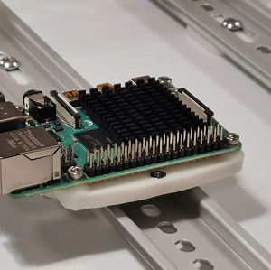
Voron 2.4 Raspberry Pi Mount for DIN Rail
G'day, another nice thingy from down under. Got non-standard electronics compartment? Some blocks there that don't allow spec placements? Don't have or don't like self-tapping screws? Or are you just up to better wiring and sturdier construction? Alright, Dropbears to rescue. Here comes a rigid bracket for Raspberry Pi, that uses M3 bolts and nuts, and allows mounting along and across the rail.
The bracket needs 1 of rs25_psu_bracket_clip.stl. (now included on the download)
Printing and Plastic
Standard Voron part printing guidelines to follow: 0.4 nozzle, 0.2 layer height, etc.
This part is not exposed to any significant heat, so you could probably use even PLA.
Assembly
BOM:
6 x M3 hex nuts 6 x M3x12 SHCS screws Pi has mount holes for M2.5 bolts, so putting M3s through might be a problem. Just enlarge these holes with 3.0mm or 3.2mm drill, you won't damage the Pi but will make your life easier.
Credits
that russian guy (aeresov#9959) A Team Dropbear Production
397 downloads
- v2.4
- raspberry-pi
- (and 3 more)
-
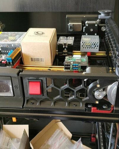
Voron 2.4 350 a/b Front Skirts for ZF Rocker Switch WRG32F2FBREN
Adapted from the original front_skirt_a_350 part to accommodate a ZF Rocker Switch WRG32F2FBREN.
The cut-out for the switch is following the manufacturer's specifications, and is tapered to make removal of the switch easier.
Left and Right versions provided.
Modded using Sketchup Pro 2022 (skp file provided).
Model is 100% watertight and easy to print.
158 downloads
-
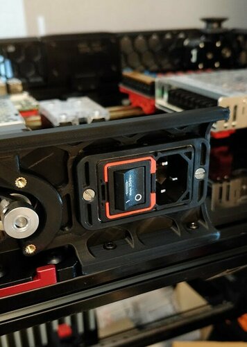
Voron 2.4 350 Schaffner FN9280 Filtered IEC Power Inlet
Adapted from the original power_inlet_IECGS_ part to accommodate a Schaffner FN9280 Ultra Compact Filtered IEC power module.
Left and Right versions provided.
Modded using Sketchup Pro 2022 (skp file provided).
Model is 100% watertight and easy to print.
The 4mm holes accept regular M3 heat inserts to secure the power module's flange (using M3x12 cone head machine screws).
56 downloads
-
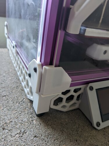
v0.1 Front Foot with door ledge
This is a replacement front left foot for the v0.1. It has a small ledge which holds the door in place, to reduce the air gap created between the tophat and the door from the filament hinge sagging. It does make the door take a little more effort to close - but it adds a feature, you can now prop open the door slightly during cooldown.
19 downloads
(0 reviews)0 comments
Submitted
-
V 0.1 ToolHead for 30x30x10 Front Fan Front Tool Head Cover
This is a mod to use 30x30x10 hot end Fan. For me it's very hard to get 30x30x07 fans, I can get just in aliexpress or other china stores. Where I live its so easy get 30x30x10 fans, so I create this mods.
113 downloads
(0 reviews)0 comments
Submitted
-
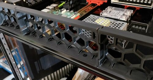
Voron 350 Side Middle Grill
[Voron 2.4 350] Open grill for the side skirt. Fits in snuggly. 2 screws.
Modified from the original models using Sketchup Pro 2022 Pro (SKP file also provided).
STL is 100% watertight and easy to print, and easy to modify to make smaller versions.
I'm sure someone else must already have made a similar one, but I couldn't find any with a lazy search.
146 downloads
-
FanSaver
MiniAB_FanSaver
A 3D-printable baffle to prevent Voron V0.1 Mini Afterburner blower fans from overheating
Is your Mini Afterburner toolhead struggling to keep up with the part cooling you request? Are you running into weird overheating artifacts despite setting absurdly high part cooling speeds? Have you noticed your blower fans slowing down or audibly changing in pitch over the course of a print?
You've come to the right place!
There is an issue that has been cropping up in some Voron V0.1 printers where the combination of high chamber temperature and radiant heat from the hotend can cause the PWM smoothing chips inside your 3010 blower fans to overheat and, as a result, can cause the fans to slow down and speed up intermittently (sometimes even coming to a full stop). In particular, the GDSTime 3010 blower fan included in the LDO V0.1 kit and similar rebranded units have a max operating temperature between 60C-70C, which can easily be exceeded by a fully heatsoaked V0.1 at ABS printing temperatures.
While there are a number of ways to overcome this issue, such as mini-heatsink installation, reflective tape, insulation, or high-temp fans, every other fix I came across was either an incomplete solution or required specialty parts / fabrication that were difficult to source or cumbersome to prepare.
The goal of this project was to make an all-in-one heat-deflecting solution that could be printed on any ABS-capable printer and installed without disassembly of your Mini Afterburner, while still requiring no additional materials or reprints / replacements of existing parts. The result is the MiniAB FanSaver: a combination air dam and heat barrier that keeps your blower fans cool with minimal time and material investment.
The print itself should only take around 20-25 minutes at moderate printing speeds and consumes approximately 3g of material. The installation is fairly straightforward and only requires cutting your two cable management zipties on the sides of the toolhead to slip the FanSaver in underneath. The installation process can be made easier by removing the toolhead from the X-carriage so you don't have to work upside-down inside your printer, but it will fit comfortably without doing so. Before starting with this modification, it is recommended to have two new zipties, a pair of flush cutters / wire cutters, a small hex key or other skinny blunt object for moving the wires around inside the toolhead, and a dental pick, needle, or similar pointy tool for removing your blower fan stickers.
The installation process is as follows:
Your hotend should be COLD for this process! Please don't try this at 245C and burn yourself. I recommend moving your toolhead to 60,0, dropping your build plate down 75-100mm, and then turning off and unplugging your machine for safety. Depending on the specific geometry of your hotend and associated silicone sock, you may have an easier time installing if you remove the silicone sock first and re-attach it after the FanSaver is in place.
(Optional) Clip all toolhead zipties, remove strain relief & stepper screws, unscrew all 5 toolhead mounting bolts, and lay toolhead face down on print surface.
Using a dental pick, needle, X-acto knife, or other pointy tool, get under the edge of the stickers on the backs of your two blower fans and peel the stickers off completely. These insulate the PWM chip from the airflow we're about to provide it, but still let through enough radiant heat that they're not providing any substantial protection in their default state. Be careful not to stab into the wiring cavities that the sticker covers.
Clip left and right cable management zip ties and pull heater and thermistor wires toward the back of the toolhead shroud.
Begin installation of FanSaver with the flat base facing down (same orientation relative to toolhead as it was printed). The semicircular scoops should be facing toward the front of the shroud / hotend fan and the rear rectangular crossbar with external tabs should face the rear of the shroud.
Press your heater and thermistor wires close to the hotend so they're between the two vertical FanSaver panels (this may require more or less wrangling with your hex key or other skinny blunt tool depending on the specific heater and thermistor you have installed and the relative thickness / stiffness of their wires).
Ride the rear crossbar's external tabs on the flat backs of the shroud like rails and slide the FanSaver into the shroud while guiding the heater and thermistor wires into the cable management channels.
Once you hit the "ceiling" of the shroud with the pointy tops of the rear columns, check for left/right alignment and then gently press the front crossbar upward and forward to lock the FanSaver into place. (If you removed your toolhead, take this opportunity to reassemble the 5 main bolts before continuing)
Pull your heater and thermistor wires taut through the cable management channels and zip tie them to the X-carriage. You don't have to go nuts here, but the presence of these wires is what locks the FanSaver in place and prevents the rear crossbar tabs from coming out of their mounting points.
You've successfully installed your FanSaver!
It's tested to be compatible with both Dragon and Dragonfly BMO hotend mounts of Mini Afterburner and Mini Aftersherpa, though likely will not fit the legacy Slice Mosquito variant of the toolhead without modification.
NOTE: Due to its proximity to the hotend, this component is a prime candidate to be printed in something more heat-resistant than ABS such as PC-ABS, CF-Nylon, or any number of more exotic plastics. Otherwise, it probably doesn't hurt to print off one or two extras to swap in if the original part ever gets melty. None of the beta testers thus far have experienced a melting or softening of the FanSaver, but that doesn't mean it can't happen down the road.
108 downloads
-
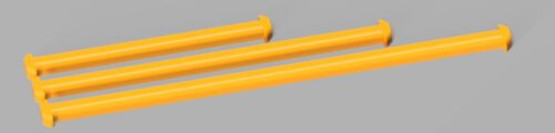
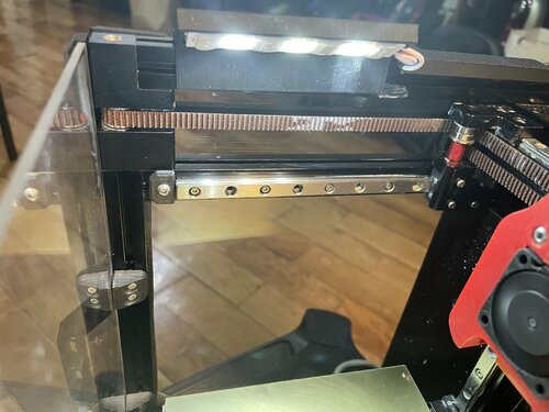
Lights, Camera, Voron
Mounts for LED strip lights and a Pi camera on the V0.1.
Details
There are three parts: a normal rail for mounting just LED strips, a rail with a mount for a Picam, and a rail with two lugs for zip ties. Each rail is 80mm long, with the intention of using two rails on each side. If you only want to mount lights, print four of the normal rail. If you also want to mount a camera, print two of the normal rails, and one each of the camera and zip tie rails.
The rails work with 8mm wide sticky-back LED strips.
Mounting the Picam using this mod is a tradeoff. It is in a relatively safe place, and provides an OK (but not great) view of printing. The camera covers most of the bed. Sometimes the mini Afterburner gets in the way of the view. Mounting the camera in the tophat would give a better view, but at the expense of needing to deal with the cable when removing the tophat.
Assembly
To install the rails, you'll need:
8x M3 hex or square nuts 8x M3x8mm screws To mount the Picam, you'll additionally need:
2x M2x6mm screws Insert the M3 nuts into the top of the top extrusions. This is pretty easy to do even after the printer is totally assembled.
Feedback
Feel free to contact me - I'm ademuri#2806 on the discord.
16 downloads
(0 reviews)0 comments
Submitted
-
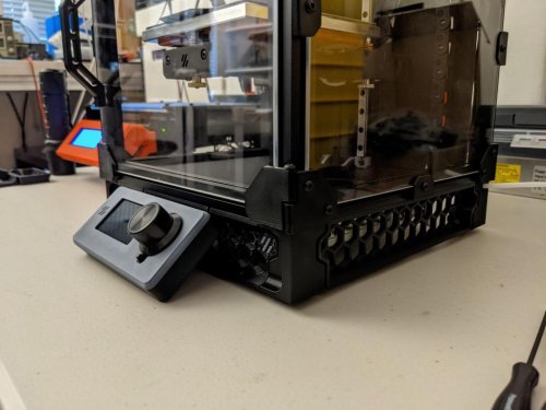
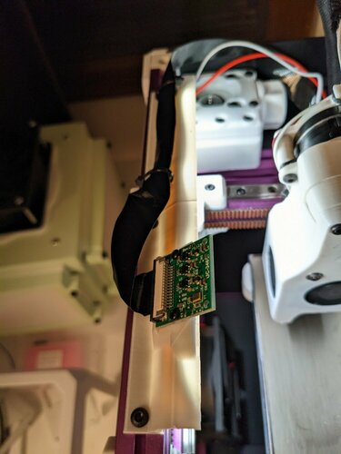
Voron 0.1 lights USB and RJ45 connector
1. Skirt mod that allows access to the Raspberry Pi's RJ45 and USB ports without opening the panels. Uses cheap panel mount USB and RJ45 connectors.
2. Light mount for LED lights which draws powered from the power supply. Light switch is besides the USB port.
26 downloads
(0 reviews)0 comments
Submitted
-
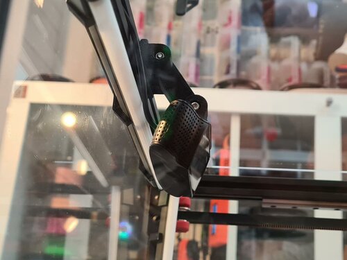
C92X PsycHoShafts Mount
Important Notes
Hello everyone,
Here is my C920 camera mod, please follow the disassembly guide below to remove the current mount off the camera. Please keep the 4 bottom screws from the mount as you will need them for my mod.
Instructions For Disassembly
Found Here!
This mod allows you to set 2 point position for your camera,
BOM
Qty Item 2 M3x40mm 1 M3x10mm 2 Nuts 1 M3 Hammerhead nut https://camo.githubusercontent.com/758a4b22a5c56662c568b7ffb24373659bc0266bcc721e882b16ef4f2bb51f16/68747470733a2f2f7777772e70617970616c6f626a656374732e636f6d2f656e5f55532f692f62746e2f62746e5f646f6e6174655f4c472e676966
246 downloads
- psychoshaft
- v1.8
- (and 2 more)
-
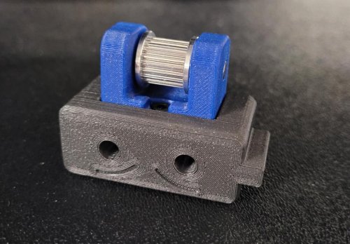
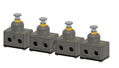
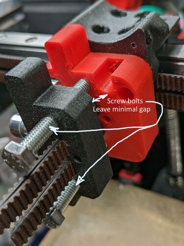
V0 Belt Tension Helper
A belt tension helper - is a tool to do pre-tension of belts
A tool act as a helper to do initial belt tension. It is able to do individual belt tension or synced tension of belts
BOM
2 or 3 M3 8mm bolts to mount helper to X-carriage
2x15mm M5 bolts to fix belts when needed
2x40mm M5 bolts and M5 nuts to perform tension
While printing use higher infill for bottom or use cylidric modifies to add strength for pads where M5 bolts will do pressure See example here:
Steps to perform:
Step 1. Mount bottom part on X carriage and push thought belts. Keep in mind that loose belt backs square nut (use holes for regulate them)
Step 2. Put top part and pass thought belts. Screw tension bolts to have zero minimal gap between bottom and top plate
Step 3. Fix belts on top part but leave loosen on bottom
Step 4. Tension belt by turning the bolts synchronously (do it sequentially by one turn for each)
Step 5. When belt are in tesion fix them using service holes by allen hex key
Step 6. Loose all M5 and unmount top and bottom tool parts
(Optional). When need to do individual belt tension use combination of bolts fix or loosen. See example for case when need to do extra tension for top belt
67 downloads
(0 reviews)0 comments
Updated
-
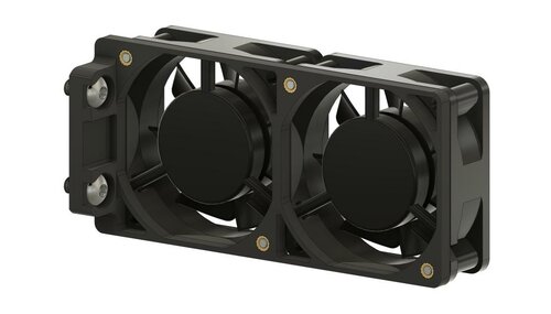
VSW Double 60mm Fan Mount
Double 60mm Fan Mount for Voron Switchwire
This is a simple mount for two 60mm fans in Switchwire's electronics compartment. It uses screws instead of VHB tape and was inspired by this mod. Of course you can also print it twice and mount four fans.
Note that using fans in this position only makes sense if you use the deck and bottom panels, as they form an air tunnel. Without them, the fans will only blow against the frame and the air will not reach the electronics.
BOM
Item Qty. Note BHCS M5x10 2 M3 Heat Set Insert 4 SHCS M3x25 4 Screw length depends on the fans used Images
41 downloads
(0 reviews)0 comments
Submitted
-
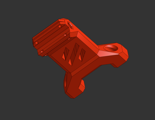
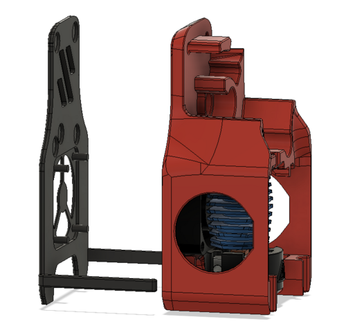
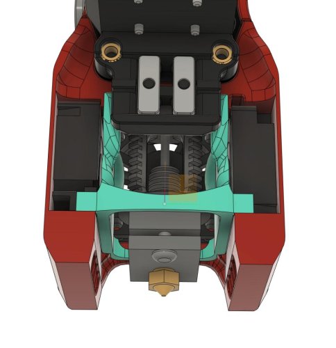
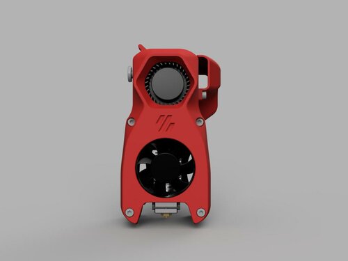
AB Turbo Mod
Voron Afterburner Turbo Mod
This is a purely cosmetic mod for the Afterburner to bring it's appearance closer to Stealthburner.
After having seen Stealthburner, Afterburner's design started to look a little dated to me. So I designed this mod. It simply replaces both of Afterburner's front parts with a single part. The only new hardware required are two shorter screws.
BOM
Item Qty. Note SHCS M3x20 2 Replace two SHCS M3x30 Images
122 downloads
- maximilian-foerg
- v1.8
- (and 3 more)
(0 reviews)0 comments
Submitted
-
HEPA Filter Exhaust
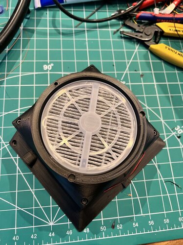
HEPA Filter Exhaust for Voron 1.x/2.x
I've designed a new exhaust which uses a 120x120x25 mm fan and HEPA filters (compatible with MELEDEN, RIGOGLIOSO, JINPUS and LTLKY air purifiers). This is a direct replacement for the stock air exhaust system.
Configured in Klipper to power the fan at 50%, and coupled with the nevermore micro, this seems to add to negative air pressure in the chamber and have a noticeable impact on reducing fumes, while only reducing chamber temperature by a couple of degrees C at the exhaust port.
Bill of Materials
New Parts
1x 120x120x25mm fan such as Noctua NF-F12 iPPC-2000. (note that I have an adjustable voltage on my control board, but make sure your fan matches the voltage for your system.) HEPA Filter such as Nispira True HEPA Filter Replacement with Activated Carbon Parts from Voron BOM
Parts here are already listed in the Voron 1.x (Trident)
161 downloads
- deprintinator
- v1.8
- (and 3 more)
-
Klipper Expander Mount
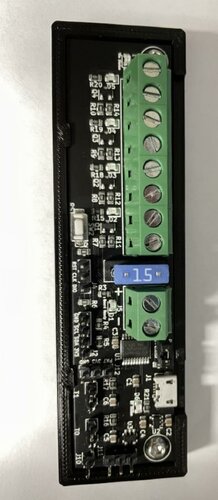
Voron-Mods
Mounting tray for the Klipper Expander Board. I didn't care for the other 2 mounts i tried. Requires 2 M3 x 6mm screws. There are 2 versions of this mount.
1: Only has a logo on the back for use with VHB tape
2: Has logo and 4 M3 countersunk holes for bhcs for mounting on rails
170 downloads
(0 reviews)0 comments
Submitted

-
Most Actively Discussed Mods
-
Hottest Files!
.thumb.jpg.2c879d60315f8d86612bb06a137c204a.jpg)