-
TeamFDM.com is an UNOFFICIAL companion site for the DIY Voron 3D printer community. For official docs and final source of truth, visit the Official Voron Discord or the Voron Github
Printable Voron User Mods
Voron User Mods, or "UserMods", are a collection of community created and Team FDM curated modification for Voron Printers. All of these mods are available on the VoronUsers Github repo and unless otherwise specified follow the Voron communities GPL3.0 Licensing. Use any Mods at your own risk, if you make modification please share them on the VoronUsers repo.
Mod Authors: Have a Voron mod? Upload it at TeamFDM.com and let us know you're the author. We will ensure you can update and curate your files for more feedback! Please include tags for what Voron, or extruder your mod is compatible with.
652 files
-

Wallmount for Voron 2.4
-------------English/Englisch-------------
Hey everyone! I whipped up this wall mount for my Voron 2.4 because I was tired of all the vibrations while printing. Plus, it keeps the printer from sliding around at high speeds. So far, it’s been awesome!
What It Does:
Flexible Use: You can mount it in any orientation. No need to mirror anything in your slicer – just print it 2x or more, depending on how many mounts you need. Cable Pass-Through: A lot of folks hide cables in the aluminum profiles, but that gets tricky when you want to screw something onto them. So, I added a cable slot to this mount – just run the cable through there. (You might need to re-crimp it, though.) Maybe for Other Printers: I made it for the Voron 2.4, but it could work with other printers using 2020 aluminum extrusion, like the Trident. Give it a shot and see! Testing Phase:
I’m currently testing it on my Voron 2.4, and it’s making a real difference. Less wobble, the printer stays put, and I think it’s even a bit quieter (since the vibrations go straight into the wall and get “swallowed” there).
Print Tips:
Filament: I printed mine in ASA (had some leftovers lying around). ABS or PETG should work fine too. PLA might do the job with a few extra wall loops. Layer Height: I went with 0.2 mm – works for me. Infill: I used 40%, but if your printer’s on the heavy side, maybe bump it up a bit. Supports: Shouldn’t need them, except maybe at the wall interface area. If so, just keep Supports on printbed only. The cable slot has some light bridging, but it’s no big deal – you can add support for better quality if you want, but it’s barely necessary. Assembly Tips:
After printing, grab 4 rotating T-nuts and 4 M3x10 screws per mount and slide them into the profile. For my setup, I placed the mounts on the left and right at the back, about 25 cm from the top of the printer. Tighten them up properly (with the 4 bolts), then mark the drill holes on the wall (use a center punch or hole marker). Drill the holes into the wall and add anchors. (Depending on your wall type, you might be able to screw straight in.) Thanks to the mount’s shape, you can easily get to all the holes and screws If you want, use the cable slot to run a cable through (like for build chamber lighting, for example).
-------------German/Deutsch-------------
Hi zusammen! Ich hab diese Wandhalterung für meinen Voron 2.4 gebastelt, weil ich die Schwingungen beim Drucken loswerden wollte. Außerdem hält sie den Drucker fest, damit er bei hohen Geschwindigkeiten nicht verrutscht. Bis jetzt echt top!
Was sie kann:
Flexibel einsetzbar: Du kannst die Halterung in jeder Orientierung verwenden. Es muss beim Druck also nichts gespiegelt werden. Einfach 2x oder öfter drucken, je nachdem wie viele Halter du benötigst. Kabeldurchlass: Viele Nutzer verstecken Kabel in den Aluminiumprofilen. Das Problem ist dann, dass die Kabel im Weg sind, wenn etwas an die Profile angeschraubt werden soll. Ich habe daher einen Kabeldurchlass mit in die Halterung eingefügt, damit man das Kabel dort einfach durchführen kann. (Möglicherweise muss man es jedoch neu Krimpen. Vielleicht auch für andere: Ich hab die Halterung primär für den Voron 2.4 erstellt, aber sie sollte theoretisch auch bei anderen Druckern mit 2020er Aluminiumprofilen funktionieren, z. B. dem Trident. Einfach mal ausprobieren! Testphase:
Ich teste sie gerade an meinem Voron 2.4, und sie macht echt einen Unterschied. Weniger Wackeln, Drucker bleibt stabil und meines Erachtens sogar etwas leiser (da die Schwingungen direkt in die Wand übertragen werden und dort “geschluckt” werden.
Druck-Tipps:
Filament: ich habe sie in ASA gedruckt (hatte noch ausreichend “Rest” da. ABS oder PETG sollten auch Funktionieren. PLA möglicherweise mit ein paar mehr Wandschleifen auch. Schichthöhe: 0,2 mm hab ich genommen Füllung: Ich habe 40% verwendet, aber bei schwereren Druckern vielleicht mehr reinpacken. Stützen: Sollten nicht notwendig sein (bis auf den Bereich des Wandinterfaces. Wenn, dann nur auf dem Druckbett. Der Kabelschlitz hat so kleines Bridging, dass es nicht notwendig ist. Für Bessere Qualität kann man es natürlich mit Support drucken, aber es sollte wie gesagt nur wenig support notwendig sein. Montage-Tipps:
Nach dem Druck dann einfach je Halter 4 rotierende Nutensteine (T-nuts) und 4 M3x10 Schrauben verwenden und in das Profil einführen. In meinem Fall habe ich die Halter links und rechts an der Rückseite positioniert, ca 25cm von der Oberkante des Druckers. Hier die Halter dann richtig Festschrauben (mit den 4 Bolzen) und die Bohrlöcher an die Wand übertragen (Körner oder Bohrloch-Marker) Die Löcher dann in die Wand Bohren und mit Dübeln versehen. (Je nachdem was für eine Wand ihr habt, könnt Ihr jedoch direkt reinschrauben) Durch die Form des Halters kommt man an alle Löcher / Schrauben bequem heran Wer will kann dann auch die Kabelführung verwenden um dort ein Kabel (zum Beispiel für die Beleuchtung des Bauraumes) hindurch zu führen.
18 downloads
(0 reviews)0 comments
Updated
-
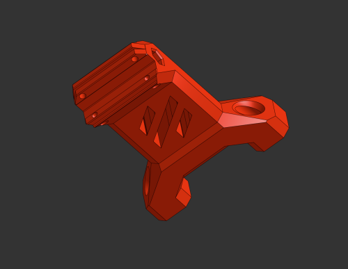
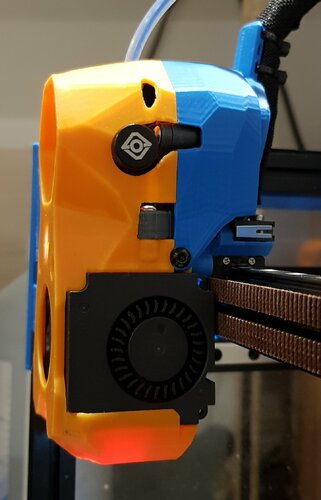
BTT CB1 Heatsink 50mm Fan Mount
The fan cover is 50x50 and powered by 5 volts from the board itself. Mounting for standard fasteners, no need to look for anything. There is also a model with the fan positioned at an angle for more optimal purging, I think that the angle can be increased even more (now 5 degrees). There is also the same model for a 40x40 fan.
14 downloads
(0 reviews)0 comments
Submitted
-
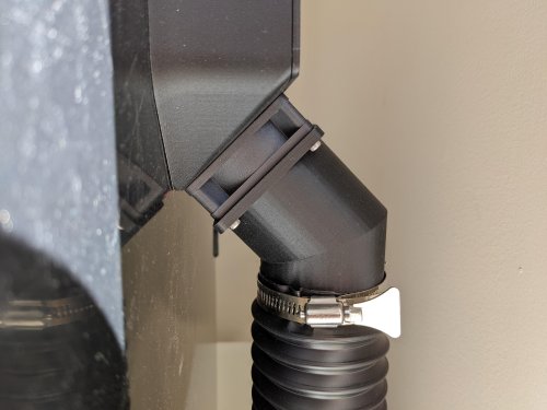
v2.4 2.4 Window Ventilation System
I wanted to be able to print ABS and ASA in my house without having to move my printer to a well ventilated area, so I started looking into ventilation options. I wasn't able to find anything that seemed to mount cleanly to my machine and look decent running to my window, so I designed this system for my printer.
BOM:
Parts to order 2.5" Hose Clamps x2 2.5" Flexible Dust Collector Hose (3ft in picture) x1 Weather Stripping (10ft in picture) M2 self-tapping screw Plastic Sheet (1.5mm-2mm) Parts to Print 60mm Fan to 2.5" Hose Adaptor x1 Hose Adaptor x1 Hose Adaptor Mount x1 One-way Valve x1 Left Link x1 Right Link x1 Center Link x? (You will need to measure your window for the proper number of links) Printing:
40% infill Supports needed 4 line walls Filament: Polymaker's Polylite ASA If you are using the stock Voron 2.4 exhaust system, you can attach the hose adaptor directly to the rear fan using the screws already holding the fan in place. All of the links snap very tightly together and may require pliers to fully seat the lock. You can also insert the one way valve into the hose adapter on the window side of the hose:
Then just attach all of the other pieces according to the images below:
Once you have everything hooked together your can wrap the window vent that is now sized for your window with the weather stripping to get a good seal on your window.
One note, I was printing several test versions of this before I got to a full system. There are couple links you will see in the center of my image that have a smaller lip on them. I just reused these from previous test pieces so I didn't waste more plastic. Your center links should be consistent all the way across the middle section of the window vent.
UPDATE:
3/9/2022 - Added a one-way valve to prevent outside air from causing a backdraft into your printer when your exhaust fan is disabled. This has made a significant impact on reducing plastic fumes in my house. After adding this, I can't smell any plastic unless the doors on the printer are open.
VORON2 v2.4 - 2.5 Vaccume exhaust adapter v4.f3d
2,412 downloads
-
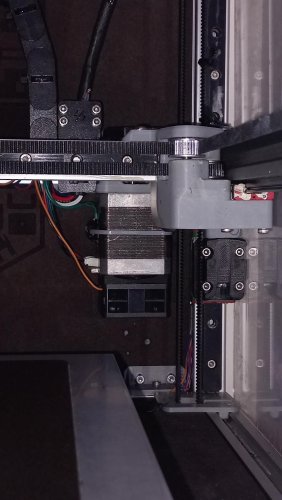
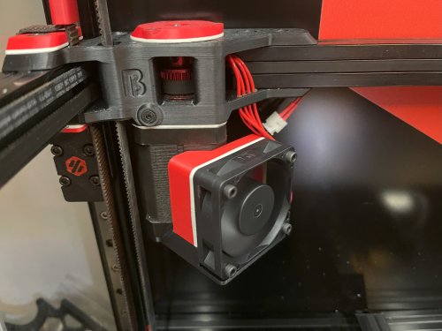
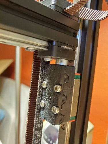
Voron 2.4 A/B Motor Fan Mount
This simple mod will give you the ability to add 4010 or 4020 fans to your AB drive motors on your Voron 2.4
Additionally you can use generic 3950 NTC for temperature controlling the fans if you have enough pin on your controller board.
I've designed my own controller board and I considered 5 NTCs so I could easily adapt to this mod.
Why I made this mod?
Personally I like to keep my motors temperature around 55-60°C for this purpose I needed active cooling, Based on tests using a high speed fan at PWM around 50% is enough to keep my motors cool while keeping fan noise to minimum. So at maximum 50% pwm for fans they are silent enough not to hear them and sufficient enough to cool motors properly.
What you will need for each motor:
2 M3x5x4 Threaded instert
1 AB Drive Fan for Voron 2.4.step
2 screws are the height of your fan + 5mm extra (for 4010 fans 3x15mm, for 4020 3x25mm. Best use BHCS).
2 screw 5mm longer than your motor screw
File are super easy to print and super easy to adapt. You'll need one fan holder per motor and one NTC holder for each NTC. Print with default voron settings and no support.
Installation:
First put 2 inserts into their designated holes in motor holder in opposite diagonals (bigger holes).
Then remove 2 diagonals screws from your motor. Preferably the one that has no screws on top side and it's diagonal one.
Measure your motor screws with a ruler or caliper and use 5mm longer screws to attach motor holder to your motor.
Now you can use 2 screws 5mm longer than your fan height to attach your fan to motor fan holder using insert you added earlier
Optionally you use ziptie and heatsink compound to attach a NTC to the body of your motor for temperature control. 200x3mm ziptie must be sufficient for this purpose. "AB Motor Thermistors Holder.stl" are for holding thermistor in place.
Here is the klipper config for controlling each fan separately based on their temperature:
#-----A MOTOR FAN---# [temperature_fan motor_a] pin: PB10 sensor_type: Generic 3950 sensor_pin: PC3 kick_start_time: 0.5 off_below: 0.1 max_power: 0.5 min_speed: 0 shutdown_speed: 0 min_temp: 0 max_temp: 150 target_temp: 55 control: pid pid_kp: 1.0 pid_ki: 0.5 pid_kd: 2.0 #-----B MOTOR FAN---# [temperature_fan motor_b] pin: PB12 sensor_type: Generic 3950 sensor_pin: PC1 kick_start_time: 0.5 off_below: 0.1 max_power: 0.5 min_speed: 0 shutdown_speed: 0 min_temp: 0 max_temp: 150 target_temp: 55 control: pid pid_kp: 1.0 pid_ki: 0.5 pid_kd: 2.0
Don't forget to change Fan and NTC pins based on your own board.
If you want to use simple control without ntcs use this code instead:
[output_pin ab_fan] pin: PB1 pwm:true shutdown_value: 0 value:1.0 cycle_time: 0.01 kick_start_time: 0.5 Don't forget to change Fan pins based on your board.
Additionally if you want you can use only one ntc for one motor and control both fans based on NTC:
#-----AB MOTOR FAN---# [temperature_fan ab_motors] pin: PB10 sensor_type: Generic 3950 sensor_pin: PC3 kick_start_time: 0.5 off_below: 0.1 max_power: 0.5 min_speed: 0 shutdown_speed: 0 min_temp: 0 max_temp: 150 target_temp: 55 control: pid pid_kp: 1.0 pid_ki: 0.5 pid_kd: 2.0 Don't forget to change Fan and NTC pins based on your own board. if you are using
Feel free to express your opinion about this mod, edit it or use it however you want
75 downloads
(0 reviews)0 comments
Submitted
-
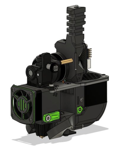
Printhead | + Rapido Hotend + vz hextrudort + EBB42 + Beacon (Right Angle)
A new version of my previous custom printhead -15% lighter.
33 downloads
(0 reviews)0 comments
Updated
-
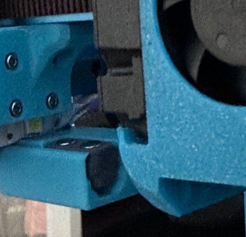
Beacon CW2 Stealthburner Alternative mounts
I've made some alternative beacon mounts for myself that i'll share
I wasn't happy with the original mount because as soon as the carriage got a bit melted the probe would start touching the heat block (see attached photo). I also believe because the probe is so close to the heater it causes the mount the deform.
I've made a mount that sits the probe back 2mm from the original but I have not tested this one, this brings me the other other mount I made.
The second mount is specific to a Dragon hotend that is rotated 180°. I did this to be able to see the nozzle better and it's now possible as there is no more probe in the way of achieving this. So far it's working well for me
I've printed my parts out of PCCF so if anyone can report their findings with an ABS mount that would be great but moving the probe should have done the trick.
The original beacon mount from annex can be found here if you were looking for that: https://github.com/Annex-Engineering/Annex-Engineering_User_Mods/tree/main/Printers/Non_Annex_Printers/VORON_Printers/VORON_V2dot4/annex_dev-stealthburner_beacon_x_carriage
1,525 downloads
- voron
- clockwork2
- (and 3 more)
-
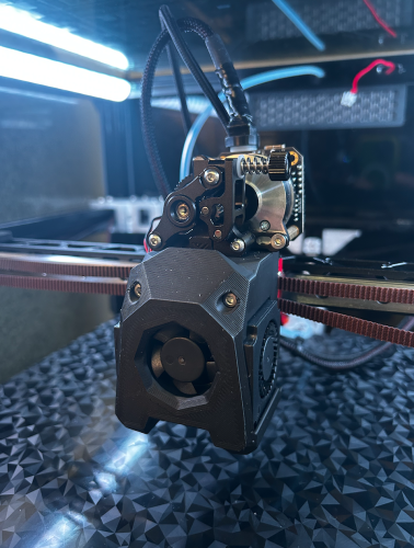
Bowden tube guide + CANBUS Wire support PTFE Arm
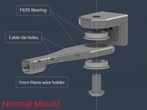
V2- PTFE bowden tube guide and CANBUS wire support
I've made some adjustment after some feedback from the community.
Changes made over V1:
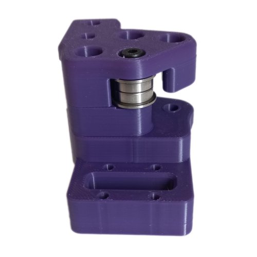
Added a option to have F695 bearings incorporated
Enlarged the tube opening
Added cable/zip tie openings
Added spot for 1mm piano wire if needed.
Recommended print settings:
Voron print settings (4 walls, 40% infill and 5 top and bottom layers)
Turn off thin walls
Bridge setting: keep only bridges (watch out for bridging for cable tie holes)
0.2mm layers and 0.2mm first layer
No need to adjust for ABS shrinkage
Required Hardware:
M3x8 Bolt and M3 T-nut
M5 bolt to suit option.
Optional M5 nut if you can fit it with the bearing option.
V1 - PTFE bowden tube guide and CANBUS wire support
This is can found inside the zip files and of the initial release
Required Hardware:
M3x8 Bolt and M3 T-nut
M5x10 Bolt or a M5x8/12
Optional 4mm drill bit for cleaning out bowden tube path
About
In my 350 build the PTFE tube kept getting caught so I made this arm to keep it up. The shorter arm works better so I recommend using it instead
The setup has also been used by a few user to support their CANBUS wires (zip tied to the reverse bowden)
Install
Drill out bowden guide with 4mm drill bit for a perfect fit (optional)
Bolt mount to rear frame with M3x8 and tnut putting the lip at the top
Screw arm on with M5x10 (I used a M5x8mm and it works fine) into the plastic allowing the arm to still be able to swivel
2,031 downloads
- canbus
- galvanicglaze
- (and 3 more)
-
Voron Trident F624ZZ Mod
Since I couldn't find any F695 where I live, I had to mod the gantry to support F624ZZ bearings instead
there are two major difference between F695 and F624 bearings but for mos parts they are identical in dimentions:
1- Inner hole of F695 is 5mm but inner hole of F624 is 4mm
2- Total width of F695 is 4mm but for F624 is 5mm
To fix these two differences we need to:
1- Use modified STLs provided with this mod
2- Use 4 M4x40 SHCS screws instead of 4 M5x40 SHCS in gantry
3- Use 4 M4x30 BHCS screw instead of 4 M5x30 BHCS in gantry
4- Use 8 M4 nut instead of 8 M5 nut in gantry
I've added small lips to prints themselves so you won't need any washer or shim for most parts, just in AB drive where four bearings are stacked on one screw between each set you'll need one or two M4 washer or shim...
I strongly suggest you use intended F695 bearings but if you are desperate like me, try this mod. I haven't had any problem with it so far. good luck
65 downloads
(0 reviews)0 comments
Submitted
-
ZeroClick side mount for Dragonburner cowl
This is a remix for those using the Dragonburner ZeroClick cowl.
I have found that the side mount in the ZeroClick repository was short by around 5mm. (The original ZeroClick design added the mount to the side of the mini-afterburner cowl) I just modified the existing probe in the ZeroClick repository (with the CAD from the repository) and lengthened it by 5mm. Tested on a Voron0.2, and can confirm it is working perfectly.
These are my probe macros (modified from the ZeroClick repo) for the V0.2
[gcode_macro ATTACH_PROBE] gcode: {% set F = 4000 %} SAVE_GCODE_STATE NAME=attach_probe_state G90 G0 Z40 G0 Y110 F{F} G0 X24 Y110 F{F} G0 X3 Y110 F{F} G0 Y110 F{F} G0 X30 F{F} G0 X60 Y60 F{F} RESTORE_GCODE_STATE NAME=attach_probe_state [gcode_macro DETACH_PROBE] gcode: {% set F = 4000 %} SAVE_GCODE_STATE NAME=detach_probe_state G90 G0 Z40 G0 Y110 F{F} G0 X24 Y110 F{F} G0 X3 Y110 F{F} G0 X3 F{F} G0 Y80 F{F} F{F} G0 X60 Y60 F{F} RESTORE_GCODE_STATE NAME=detach_probe_state
13 downloads
(0 reviews)0 comments
Updated
-
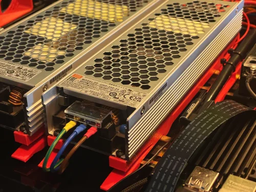
Mean Well UHP-500-XX PSU DIN Rail Mount
A DIN Rail Mount for a Mean Well UHP-500-XX Power Supply that attaches across two DIN Rails.
Print Instructions:
I've used the usual Voron 0.2mm Layer Height, 4x Perimeter, 5x Top / Bottom Layers, and 40% Infill Settings which should work for anything using Heat Set Inserts.
The Models come with in the Slicer added Mouse Ears to help with bed Adhesion - If you don't need them just remove the “Generic-Disk”
BOM ( for a Set of Two ) :
4x Voron Style M3x4mm Heat Set Inserts 8x M3x10mm Button Head Cap Screws 4x M3 Washers Assembly:
Install two M3x10mm Button Head Cap Screws with the M3 Washers ( marked in blue ) into the bottom of the Mounts acting as Reinforcements for the Hooks - The PSUs turned out to be surprisingly heavy and I didn't want to risk the weight of them pulling down on the Hooks causing the latter to become loose.
Install two Voron Style M3x4mm Heat Set Inserts ( marked in blue ).
The one behind the Securing Latch is a bit hard to get into - Use a longer M3 to help pull it in.
Attach the Mean Well UHP-500-XX Power Supply to the Mounts using the remaining M3x10mm Button Head Cap Screws.
Attach the Assembly to the DIN Rails with a sliding motion while pressing down at the end with the Securing Latches.
To remove the Assembly, pull the Latches slightly up followed by sliding it back out.
Word of Caution:
This Design requires the distance between the DIN-Rails to be of proper length!
Too far apart and the rear Hook will prevent the Locking Mechanism from properly seating onto the front Rail.
Too close together and the rear Hook might not catch.
As such perhaps consider using the Mounts themselves with setting up the required distance between the DIN-Rails.
9 downloads
(0 reviews)0 comments
Updated
-
Mean Well UHP-350-XX PSU DIN Rail Mount
A DIN Rail Mount for a Mean Well UHP-350-XX Power Supply that attaches across two DIN Rails.
Print Instructions:
I've used the usual Voron 0.2mm Layer Height, 4x Perimeter, 5x Top / Bottom Layers, and 40% Infill Settings which should work for anything using Heat Set Inserts.
The Models come with in the Slicer added Mouse Ears to help with bed Adhesion - If you don't need them just remove the “Generic-Disk”
BOM ( for a Set of Two ) :
4x Voron Style M3x4mm Heat Set Inserts 8x M3x10mm Button Head Cap Screws 4x M3 Washers Assembly:
Install two M3x10mm Button Head Cap Screws with the M3 Washers ( marked in blue ) into the bottom of the Mounts acting as Reinforcements for the Hooks - The PSUs turned out to be surprisingly heavy and I didn't want to risk the weight of them pulling down on the Hooks causing the latter to become loose.
Install two Voron Style M3x4mm Heat Set Inserts ( marked in blue ).
The one behind the Securing Latch is a bit hard to get into - Use a longer M3 to help pull it in.
Attach the Mean Well UHP-350-XX Power Supply to the Mounts using the remaining M3x10mm Button Head Cap Screws.
Attach the Assembly to the DIN Rails with a sliding motion while pressing down at the end with the Securing Latches.
To remove the Assembly, pull the Latches slightly up followed by sliding it back out.
Word of Caution:
This Design requires the distance between the DIN-Rails to be of proper length!
Too far apart and the rear Hook will prevent the Locking Mechanism from properly seating onto the front Rail.
Too close together and the rear Hook might not catch.
As such perhaps consider using the Mounts themselves with setting up the required distance between the DIN-Rails.
21 downloads
(0 reviews)0 comments
Updated
-
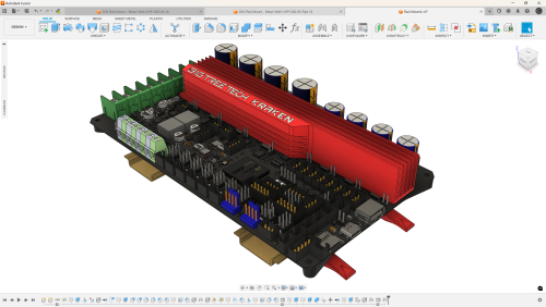
BigTreeTech KRAKEN DIN Rail Mount
A DIN Rail Mount for a BigTreeTech KRAKEN Controller Board that attaches across two DIN Rails.
Print Instructions:
The Board Mounting Part is a MultiColor Part for those that fancy it.
I've used the usual Voron 0.2mm Layer Height, 4x Perimeter, 5x Top / Bottom Layers, and 40% Infill Settings which should work for anything using Heat Set Inserts.
Some parts of the Model come with in the Slicer added Mouse Ears to help with bed Adhesion - If you don't need them just remove the “Generic-Disk”
BOM:
4x Voron Style M3x4mm Heat Set Inserts 4x M3x8mm Flat Hat Cap Screws 4x M3.5x8mm Self Tapping Button Head Screws Assembly:
Add 2x Voron Style M3x4mm Heat Set Inserts per Rail Mount ( marked in blue ).
Use 4x M3x8mm Flat Hat Cap Screws to attach the Board Mount to the Rail Mounts ( marked in blue ).
Use 4x M3.5x8mm Self Tapping Button Head Screws to secure the BTT KRAKEN to the Board Mount.
Attach the Assembly to the DIN Rails with a sliding motion while pressing down at the end with the Securing Latches ( BTT KRAKEN removed for better visibility ).
To remove the Assembly, pull the Latches slightly up followed by sliding it back out.
Word of Caution:
This Design requires the distance between the DIN-Rails to be of proper length!
Too far apart and the rear Hook will prevent the Locking Mechanism from properly seating onto the front Rail.
Too close together and the rear Hook might not catch.
As such perhaps consider using the Mounts themselves with setting up the required distance between the DIN-Rails.
36 downloads
- bigtreetech
- kraken
- (and 1 more)
(0 reviews)0 comments
Updated
-
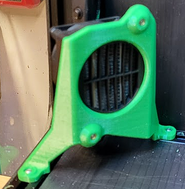
Voron 60mm Stepper FAN Mount
A Mount for installing a 5015 FAN ( like a SUNON MF50152V2-1000U-A99 ) with 40mm Hole Spacing to a 60mm Stepper Motor ( like the LDO-42STH60-3004MAC (S40) )
I tried using Double Sided Tapes and Magnets but neither of them were a reliable Solution so here's a Version that securely mounts it to the Stepper Motor without using the Stepper Motor Screws.
BOM ( for a Set of two ) :
8x M3x4mm Voron Style Heat Set Inserts
8x M3x20mm Button Head Cap Screws
4x M3x12mm Button Head Cap Screws
Print Instructions:
The Parts come as Multi Color Parts for those that fancy it.
I've used the usual Voron 0.2mm Layer Height, 4x Perimeter, 5x Top / Bottom Layers, and 40% Infill Settings which should work for anything using Heat Set Inserts.
Perhaps use a Brim for the Air Guides since they barely make any contact with the Bed.
Installation Instructions:
Install two M3x12mm Button Head Cap Screws that will hold the Mount to the Stepper into the Fan Mount - It helps doing this while the Stepper has not yet been installed to gauge how far the Screws will have to be threaded into the Mount.
Install the Voron Style M3x4mm Heat Set Inserts into both the Fan Mount and the Air Guides.
Use the Fan to Assemble the Air Guides and Fan Mount into a unit using M3x20mm Button Head Cap Screws - Be mindful of a suitable Fan Cable Orientation that works for your Setup.
Slide the Fan Mount onto the Stepper with the Screw closest to the Fan catching onto the Stepper Motors Bottom Plate first, then rotate the Mount so that the rear Screw will catch as well.
⚠ Caution ⚠:
This was tested with a Chaoticlab CNC Tap V2.0 and no MicroSwitch Endstop Mount attached to it! ( Sensorless Homing! )
This AddOn may not work with any X-Carriers having Parts occupying the space below the X-Axis Extrusion as the FANs now partially do!
21 downloads
(0 reviews)0 comments
Updated
-
Voron 2.4 Exhaust fan silencer
Attention to all Voron users, is there anyone here who wishes for a more silent fan for their exhaust system? Look no further, as we have the ideal answer integrated into all our Voron printers. It ensures the required airflow while notably decreasing the noise produced by the exhaust fan. This is an essential upgrade for individuals who utilize their printers in office environments.
If you like the work I do here at 3D Magic feel free to have a look at some of my other designs :
https://cults3d.com/en/users/ThreeDMagic/3d-models
Print settings:
Material ABS Layer Hight 0.2 or less Parimeters 3 Infill 20% (lines)
137 downloads
-
Voron 2.4 controller fan silencer
Attention all Voron users, who among you can attest to desiring a quieter fan for their controller cooling system?
Search no more, as we have the perfect solution implemented across all our Voron printers. It maintains the necessary airflow while significantly reducing the noise generated by the fans. This is a crucial addition for those who operate their printers in workspaces.
If you like the work I do here at 3D Magic feel free to have a look at some of my other designs :
https://cults3d.com/en/users/ThreeDMagic/3d-models
Print settings:
Material ABS Layer Hight 0.2 or less Parimeters 3 Infill 20% (lines)
78 downloads
(0 reviews)0 comments
Updated
-
Voron2.4 GE5C Z Joint Remix
Update 6/29/2024: See comments - Thanks to Egorka555 (at Printables) for a fix to a problem with triggering the y-endstop when using these, since they have a lower profile than the stock joints. Egorka555 gave permission to add the fix to this design. To use the fix, just install it over the Z-joint which is used to actuate the Y-endstop (rear right). The files are named “y-stopper.stl" and ”y-stopper.step". Please see the pics on how to install the add on part, which will require longer M3 screws. There is currently no option for Hall effect endstops, only the mechanical switch endstops.
I'm mostly moved over to Printables now, so you can check there for updates as well.
This is a remix of Hartk1213's Voron2.4 GE5C Z Joint.
https://github.com/VoronDesign/VoronUsers/tree/master/printer_mods/hartk1213/Voron2.4_GE5C
Update 5/27/2023: Thanks to the comments and concerns regarding this from reddit, especially the strength of the split joint, I redesigned this so it should be stronger (certainly feels stronger). To strengthen the split part, I moved the split up towards the top (instead of along the center of the bearing. I suggest using some superglue and it should be very strong (I had to cut the bearing out of one).
Update 6/16/2023: After thinking about this a bit, I am not sure if this is an ideal solution since the joints need some x-y play in order to operate (think of it like a door swinging through it's arc, if you held the door at the door handle you would be pulled as it opened).
Update 8/11/2023: My first idea to make a remix was not very good, so I'm looking to see if I can make a Z joint that won't use the GE5C bearings at all. That idea may or may not ever see the light of day, so if you like the idea of the GE5C mod, then this model is an option.
The original design from Hartk1213 is great, and this is just a different take on it. The primary difference is that the bearing is moved up (higher than the MGN9 carriage), and back just a fraction of a mm (which would otherwise interfere with the carriage). The reason for moving it up and back was to keep it in alignment with the lower belt clip from Voron CAD file. With this design, I was also hoping to hold the bearing in place in all directions, and it seems to be very well held in the parts I printed (there is no play). But to allow for a printable part, I had to split the joint. The split is designed with a lot of surface area where glue can be applied, to better hold it together.
This design is an almost ground up remix, so some dimensions are changed from the original model. I used the STEP file from the Voron Github to assist with setting up the alignment of the parts.
There are two versions provided:
The basic version has no locking tabs and can be assembled using glue. This version is named “Voron_GE5C Z joint_REMIX-4H.stl”. The other version is designed with locking clips (this is the version I used). It is named “Voron_GE5C Z joint_REMIX-4H-CLIPS.stl”, and is also designed to be glued. I feel this version will be a bit stronger, since it has a mechanical connection as well. The clip version will need a bit of persuasion to snap together (I just gave it a good couple of hits on the desktop, but closing it in a vice may also work). If you don't have luck snapping it together, try the basic version. BOM (for each z-joint)
(1) M5x25mm BHCS (though other lengths will work with different spacers) (4) M3x16 SHCS to mount the joint to the Z-carriages (1) GE5C bearing (see note below about the cheap ones) (2-3) M5 1mm spacers (or washers if they are similar in size) Optionally you can use some M5 aluminum spacers instead of the washers, and different length M5 screws. In the parts pictured, I used M5x25mm screws, and some M5x8x5mm spacers (though I plan to swap them for M5x8x3mm spacers). Note that the number of spacers and length of screws will depend on the stack height of your lower belt clips + the thickness of the AB joints and the tensioners. So YMMV, and I recommend measuring your parts before deciding on a proper length of M5 screw, and how many spacers or washers will work in your particular application.
I recommend printing these in ABS with 100% infill and supports touching the build plate. You may be able to get away with no supports if you have your settings tuned and your printer can print bridges without issues. Additionally, (in Cura) I used Slicing Tolerance “Exclusive” and set the Wall Ordering to “Outside to Inside", which helps to produce parts which are closer to the designed size. It is a good idea to run a flow calibration and horizontal expansion calibration prior to printing these, which will also help if you find the parts do not fit the bearing well. The parts should be oriented as shown. After printing, poke out the single layer of bridge material in the mounting holes to clear them for the M3 screws.
The parts are not oriented for printing.
As pictured, I am using M5x25 BHCS, as well as a 5mm M5 spacer (which I plan to swap for a 3mm M5 spacer). I also ordered some IGUS GE5C bearings since I found that more than half the bearings in the pack of no-spec GE5C bearings I got from Ali, have very noticeable play. I found 4 that were OK enough to install, but they will be replaced with the IGUS bearings at some point (the IGUS bearings have zero noticeable play). You can also find ABEC-7 rated GE5C bearings a bit cheaper on West3d.com (but for the price difference I'd just get the IGUS bearings). I'm still in the process of building my Voron 2.4 R2, which is slow going since I keep finding things to make or remix for it (that is not a complaint :D). So I have not fully tested this, but I did re-align the gantry after installing these and found no issues with interference.
If you like this, please post a make over on Printables, which will get me a bit closer to my first spool of Prusament. Please also provide feedback which may help to improve the design if I have time to revisit it in the future. There is currently no hall effect (magnet) version of this model.
The STEP file is included for easy remixing.
You can see what other projects I have going on by checking out my blog here. I'm also documenting my Voron 2.4 R2 build here (but it's been a slow going process).
y-stoper.step y-stoper.stl
266 downloads
-
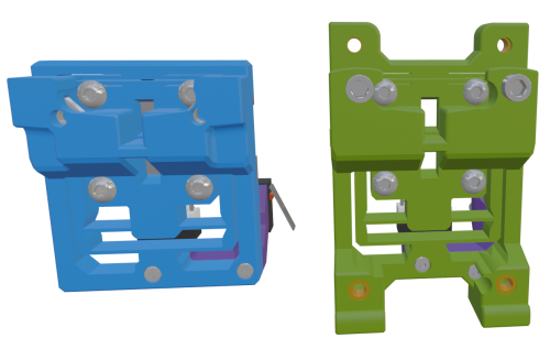
Mini Stealth DAB - Beta Release
This x-carriage is designed as a nozzle probing option for mounting a Mini Stealth in a Voron Trident or V2.4. It uses a simple linear compliant mechanism to allow minimal Z travel while being quite rigid in the other five degrees of movement. Completely assembled including Z and X endstops it weighs in at 18g. It should require the same Print_Start preparations as the Voron TAP to ensure a clean nozzle and accurate probing.
On my Vorpal 180 printer I got sub 0.002mm probe_accuracy results while testing but this design does require a rigid gantry and print bed. While probing with a scale on top of the bed, it was reading up to 800g of force but this is not a very reliable measurement. The Vorpal printer has a PCB style bed and no 2020 profile for the gantry. I am working to rebuild the toolhead on my Trident to test the DAB but that uses a Prusa PCB bed as well.
There are breakable supports and bed adhesion aids (shown in green in the last picture) built into the .stl file. After printing, the flexure feature will need to be pried slightly to separate the center section from the bridge that the toolhead mounts to and allow movement. This is easier to do while the part is still warm from printing and a thin spudger can be useful.
I have added two sample flexures to demonstrate how the length of the web pieces effect the stiffness of the mechanism.
Parts Required:
Mini_Stealth_DAB_ver0.6
DAB_Z_Stop_Boss(X_Stop)
2 - M3 x 4 grub screws (not pointed)
4 - M2 x 10 self tapping screws (5 if X endstop)
1 - microswitch with lever removed
2 - M3 square nuts
4 - M3 x 12 BHCS
Assembly:
After ensuring that the flexure moves freely, install one of the grub screws in the top and screw it in just enough to remove the looseness in the flexure. This provides a known lower limit of travel. Install the Z_Stop_Boss with two M2 x 10 screws from the front. Then install the Z micro-switch with the red trigger on the left (viewed from the back). The wires can be fed to the front through the lower gap in the flexure. Install the other M3 grub screw on the bottom of the DAB_Z_Boss. Screw it in until you hear the micro-switch trigger and then turn it back out until the trigger releases. This makes the trigger travel distance less than 0.5mm. Mount the x-carriage to the MGN12C carriage with four M3x12 BHCS. There is room to pull the four belt ends through and trim them at the front face of the DAB. This design will now fit all of the Mini Stealth v2 variations. The extruders have each been raised as needed to avoid the prior collisions with the top of the flexure frame.
Stealthburner Version:
This version of the DAB is a drop-in replacement for the Stealthburner x-frame pieces. It uses slightly different hardware than the official Stealthburner assembly, as shown in the picture below.
Please leave comments, questions and feedback.
150 downloads
- voron
- stealthburner
- (and 4 more)
-
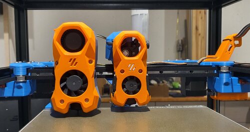
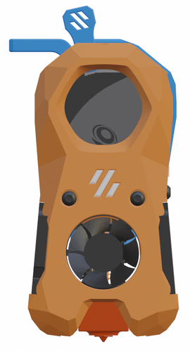
Mini Stealth - Orbiter 1.5
The Mini Stealth v2 toolhead is up on GitHub now. I will keep these files here as the new parts are not compatible with the v1.2.5 parts. I will support both versions in the comments here. I still need to create new assembly instructions but a lot of the steps are similar to what is described here.
---------------------------------------------------------------------------
This toolhead scales down the body of the Stealthburner to a size which fits into a V0.1/V0.2. Fully assembled it weighs about 80 grams less than the original. It is designed around the Orbiter 1.5 extruder and has versions for the Phaetus Dragonfly, Dragon and Rapido HF hotends as well as versions for the Mosquito and the Revo Voron hotends. It incorporates a status LED as well as two for print visibility.
There are now two hex pattern inlays based on the design by 3DP-MAMSIH and a tutorial on how to apply them to the shroud. The negative body feature of Prusa/Super Slicer can also be used to create a crop-top version of the shroud as described at the end of the tutorial.
I have added new stretched versions that should fit the Rapido UHF, Dragon UHF and the VolcoMosq hotends. The Dragon UHF and Rapido UHF hotends can fit in the same shroud. The UHF hotends will reduce Z travel by 8.5mm and the VolcoMosq by 3mm. I cannot verify the fitment so if there are any issues please leave a comment.
It uses a pair of 4010 blowers which I found to produce more airflow than a 5015 blower while being notably less noisy and drawing less current. The depth of these fans do limit Y travel by 3mm on a V0.1 while the door is closed and tophat is on. The width of the main body at its base is also a very tight fit at the extremes of X travel. I have raised my tophat by 20mm which gives the cabling and filament tube plenty of room to breathe. The shroud fits a 3010 hotend fan or a 3007 fan by using a clip-in adapter.
I have also installed this on my Trident. The included files do not address cable management on a Trident or V2.4 but do provide mounting to the MGN12 carriage. The cable chain on a Trident or V2.4 would have to be moved back at least 5mm to clear the extruder stepper motor. There is a separate 'strain_relief' stl for use in the V0.1. There are also x-frame pieces that allow this Mini Stealth to be installed on a Switchwire. The nozzle is moved up by 3mm compared to the official Switchwire due to the stepper motor being so low on the Orbiter extruder but this also allows a BL-Touch to fit into the x-frame pieces.
I have included a magnet mount and additional shroud .stl files to make this compatible with the ZeroClick mod. This toolhead also has versions that allow mounting a differential IR sensor. I have removed the mechanical Z endstop on my V0.1 and use the IR probe as an endstop and it has greatly simplified my homing sequence. There are additional x-frame pieces that allow mounting the Beacon3D probe, Euclid or Biqu MicroProbe for a V2.4, Trident or Switchwire.
The included Blender file shows the entire assembly complete with screws and should answer most basic questions.
Note on MGN-9 installation:
The default 2mm x 10 plastic threading screw is too long for mounting the x-axis endstop. An M2 x 8 does the job fine. For mounting to the linear carriage use four M3 x 6 flat-head screws.
Note: The MGN carriage shown is an MGN-9H, not the shorter MGN-9C used in the V0.1 mod.
Preparation
I recommend using a file to lightly remove any printing artifacts on the mating face of the shroud.
Use a small file to smooth out the break-off edges of the LED PCB and make sure the LED pockets are clear of 'droopy bits'
All three fans will need the wire retention piece clipped so the wires fit into the shroud channels easier.
Differential IR Probe Installation
The IR Probe needs to be screwed into place with two M2.5x8 FHCS before installing any of the fans, except with the VolcoMosq or UHF hotends where the probe needs to be glued on with CA glue. The Y-offset for this probe is 4mm in front of the nozzle and the X-offset is 32mm.
I strongly recommend removing the 3-pin header and soldering wires directly to the probe PCB.
When installed the wires will route out from the back of the IR probe cover to then join with the hotend and fan wires.
I have included a cover to allow a connector at the probe but the wire management will be less than ideal..
Assembly Instructions
After pressing the status LED diffuser into place, install the right part-cooling fan first by feeding the wires through the small hole at the bottom. Then feed the wires for the status LED and hotend fan through before starting to push the LED carrier into position.
Carefully push the status LED carrier as far as it will go and press the fan into position while making sure not to pinch the part-cooling fan wires. Then press the remaining LEDs into their slots. (I measure out 35mm of wire to connect these LEDs together)
Here is another view also showing where the hotend fan wires fit.
Insert the second part-cooling fan and splice the wires together with the first fan.
Install the hotend with at least two M2.5x6 screws (M3x6 for the Revo Voron). The heater cartridge should be installed away from the LEDs to avoid overheating them.
( ** don't forget the PTFE tube )
Gather the wires together and secure them with the first zip-tie.
(it helps to insert a snipped zip-tie through the the hole and yank it through with pliers to remove printing artifacts from inside of the channels)
Loop the wire bundle back around and add in the LED and hotend fan wires. Use two more zip-ties to secure everything in place. ENSURE to leave room for the extruder by lifting the loop of wires up and out of the way as shown. More space is much better than not enough. (Don't forget the PTFE tube)
Pre-assemble the extruder pieces before installing into the shroud. Use two M3x8 BHCS to install the Orbiter 1.5 extruder. It helps to have both screws in the Orbiter before putting it in place. Start the screw by the latch and then the blind screw should be easier to align.
Gather all of the wires together and then use a zip-tie to secure them to the motor-bridge. Leave a little slack in the extruder wires.
Install the strain_relief with two M3x6/8 screws and the cable_door with a M3x10/12 screw.
Close the cable door with a M3x6 screw and screw in the extruder tensioning thumb screw.
Use two M3x40 BHCS to secure the toolhead to the x-carriage in a V0.1/V0.2. For installation in a Trident or V2.4 use two M3x50 BHCS.
Happy Printing!
13,495 downloads
-
Mini Stealth - LGX Lite
The Mini Stealth v2 toolhead is up on GitHub now. I will keep these files here as the new parts are not compatible with the v1.2.5 parts. I will support both versions in the comments here. I still need to create new assembly instructions but a lot of the steps are similar to what is described here.
---------------------------------------------------------------------------
This toolhead scales down the body of the Stealthburner to a size which fits into a V0.1/V0.2. Fully assembled it weighs about 120 grams less than the original. It is designed around the Bondtech LGX Lite extruder and has versions for the Phaetus Dragonfly, Dragon and Rapido HF hotends as well as versions for the Mosquito, the Revo Voron and the Creality Spider Pro hotends. It incorporates a status LED as well as two for print visibility.
I have added new stretched versions that should fit the Rapido UHF, Dragon UHF and the VolcoMosq hotends. The Dragon UHF and Rapido UHF hotends can fit in the same shroud. The UHF hotends will reduce Z travel by 8.5mm and the VolcoMosq by 3mm. I cannot verify the fitment so if there are any issues please leave a comment.
There are now two hex pattern inlays based on the design by 3DP-MAMSIH and a tutorial on how to apply them to the shroud. The negative body feature of Prusa/Super Slicer can also be used to create a crop-top version of the shroud as described at the end of the tutorial.
The shroud uses a pair of 4010 blowers which produce more airflow than a 5015 blower while also being notably less noisy and drawing less current. The depth of these fans do limit Y travel by 3mm on a V0.1 while the door is closed and tophat is on. The width of the main body at its base is also a very tight fit at the extremes of X travel. The shroud fits a 3010 hotend fan or a 3007 fan by using a clip-in adapter.
The Mini Stealth LGX Lite fits well in a V2.4 or Trident and modified x-frame left and right pieces are included. There is a separate 'strain_relief' stl for use in the V0.1. There are also x-frame pieces that allow this Mini Stealth to be installed on a Switchwire. The nozzle is moved up by 3mm compared to the official Switchwire. The x-frame has geometry that allows a BL-Touch to fit locked between the two pieces.
I have included a magnet mount and additional shroud .stl files to make this compatible with the ZeroClick mod. This toolhead also has versions that allow mounting a differential IR sensor. I have removed the mechanical Z endstop on my V0.1 and use the IR probe as an endstop and it has greatly simplified my homing sequence. There are additional x-frame pieces that allow mounting the Beacon3D probe, Euclid or Biqu MicroProbe for a V2.4, Trident or Switchwire.
The included Blender file shows the entire assembly complete with screws and should answer most basic questions.
Note on MGN-9 installation:
The default 2mm x 10 plastic threading screw is too long for mounting the x-axis endstop. An M2 x 8 does the job fine. For mounting to the linear carriage use four M3 x 6 flat-head screws.
Note: The MGN carriage shown is an MGN-9H, not the shorter MGN-9C used in the V0.1 mod.
Preparation
I recommend test fitting the extruder, LGX_lite_adapter_plate, PTFE tube and hotend into the shroud before running any wires to ensure that the PTFE tube length is correct and everything fits. It helps to chamfer the edge of the tube with a sharp blade so that it doesn't snag in the hotend.
I is a good idea to use a file to lightly remove any printing artifacts on the mating face of the shroud.
All three fans will need the wire retention piece clipped so the wires fit into the shroud channels easier.
Use a small file to smooth out the break-off edges of the LED PCB and make sure the LED pockets are clear of 'droopy bits'
Differential IR Probe Installation
The IR Probe needs to be screwed into place with two M2.5x8 FHCS before installing any of the fans, except with the VolcoMosq or UHF hotends where the probe needs to be glued on with CA glue. The Y-offset for this probe is 4mm in front of the nozzle and the X-offset is 32mm.
I strongly recommend removing the 3-pin header and soldering wires directly to the probe PCB.
When installed the wires will route out from the back of the IR probe cover to then join with the hotend and fan wires.
I have included a cover to allow a connector at the probe but the wire management will be less than ideal..
Assembly Instructions
After pressing the status LED diffuser into place, install the right part-cooling fan first by feeding the wires through the small hole at the bottom. Then feed the wires for the status LED and hotend fan through before starting to push the LED carrier into position.
Carefully push the status LED carrier as far as it will go and press the fan into position while making sure not to pinch the part-cooling fan wires. Then press the remaining LEDs into their slots. (I measure out 35mm of wire to connect these LEDs together)
Here is another view also showing how the hotend fan wires fit through the hole on the side of the status LED carrier.
Insert the second part-cooling fan and splice the wires together with the first fan.
Install the hotend with at least two M2.5x6 screws (M3x6 for the Revo Voron). The heater cartridge should be installed away from the LEDs to avoid overheating them.
( ** don't forget the PTFE tube )
Pre-assemble the extruder pieces before installing into the shroud. Use M3x30 screws to attach motor_bridge.
Install the extruder with an M3x6 BHCS on the back and then an M3x12 from below.
Ensure the cables are routed as flat to the shroud as possible and secure them with zip ties.
Install the strain_relief or cable_chain_mount with two M3x8 screws and the cable_door with another M3x8 screw. Close the cable door with an M3x6 screw.
Use two M3x40 BHCS to secure the toolhead to the x-carriage in a V0.1/V0.2. For installation in a Trident or V2.4 use two M3x50 BHCS.
Happy Printing!
22,243 downloads
- lgx lite
- stealthburner
- (and 19 more)
-
Mini Stealth - Mini Sherpa
The Mini Stealth v2 toolhead is up on GitHub now. I will keep these files here as the new parts are not compatible with the v1.2.5 parts. I will support both versions in the comments here. I still need to create new assembly instructions but a lot of the steps are similar to what is described here.
---------------------------------------------------------------------------
This toolhead scales down the body of the Stealthburner to a size which fits into a V0.1/2. Fully assembled it weighs less than 260 grams. It is designed around the Mini Sherpa extruder and has versions for the Phaetus Dragonfly, Dragon and Rapido HF hotends as well as versions for the Mosquito, the Revo Voron and the Creality Spider Pro hotends. It incorporates a status LED as well as two for print visibility.
I have also added stretched versions that should fit the Rapido UHF, Dragon UHF and the VolcoMosq hotends. The Dragon UHF and Rapido UHF hotends can fit in the same shroud. The UHF hotends will reduce Z travel by 8.5mm and the VolcoMosq by 3mm. I cannot verify the fitment so if there are any issues please leave a comment.
There are now two hex pattern inlays based on the design by 3DP-MAMSIH and a tutorial on how to apply them to the shroud. The negative body feature of Prusa/Super Slicer can also be used to create a crop-top version of the shroud as described at the end of the tutorial.
The shroud uses a pair of 4010 blowers which produce more airflow than a 5015 blower while also being notably less noisy and drawing less current. The depth of these fans do limit Y travel by 3mm on a V0.1 while the door is closed and tophat is on. The width of the main body at its base is also a very tight fit at the extremes of X travel. The shroud fits a 3010 hotend fan or a 3007 fan by using a clip-in adapter.
This Mini Stealth - Mini Sherpa also fits well in a V2.4 or Trident and modified x-frame left and right pieces are included. There are cable chain mounts as well as strain_relief and umbilical_PCB mount for use in the V0.1. There are additional x-frame pieces that allow this Mini Stealth to be installed on a Switchwire. The nozzle is moved up by 3mm compared to the official Switchwire. The x-frame has geometry that allows a BL-Touch to fit locked between the two pieces.
I have included a magnet mount and additional shroud .stl files to make this compatible with the ZeroClick mod. This toolhead also has versions that allow mounting a differential IR sensor. I have removed the mechanical Z endstop on my V0.1 and use the IR probe as an endstop and it has greatly simplified my homing sequence. There are additional x-frame pieces that allow mounting the Beacon3D probe, Euclid or Biqu MicroProbe for a V2.4, Trident or Switchwire.
The included Blender file shows the entire assembly complete with screws and should answer most basic questions.
Note on MGN-9 installation:
The default 2mm x 10 plastic threading screw is too long for mounting the x-axis endstop. An M2 x 8 does the job fine. For mounting to the linear carriage use four M3 x 6 flat-head screws.
Note: The MGN carriage shown is an MGN-9H, not the shorter MGN-9C used in the V0.1 mod.
Preparation
I recommend using a file to lightly remove any printing artifacts on the mating face of the shroud.
Use a small file to smooth out the break-off edges of the LED PCB and make sure the LED pockets are clear of 'droopy bits'
All three fans will need the wire retention piece clipped so the wires fit into the shroud channels easier.
Differential IR Probe Installation
The IR Probe needs to be screwed into place with two M2.5x8 FHCS before installing any of the fans, except with the VolcoMosq or UHF hotends where the probe needs to be glued on with CA glue. The Y-offset for this probe is 4mm in front of the nozzle and the X-offset is 32mm.
I strongly recommend removing the 3-pin header and soldering wires directly to the probe PCB.
When installed the wires will route out from the back of the IR probe cover to then join with the hotend and fan wires.
I have included a cover to allow a connector at the probe but the wire management will be less than ideal..
Assembly Instructions
After pressing the status LED diffuser into place, install the right part-cooling fan first by feeding the wires through the small hole at the bottom. Then feed the wires for the status LED and hotend fan through before starting to push the LED carrier into position.
Carefully push the status LED carrier as far as it will go and press the fan into position while making sure not to pinch the part-cooling fan wires. Then press the remaining LEDs into their slots. (I measure out 35mm of wire to connect these LEDs together)
Here is another view also showing how the hotend fan wires fit through the hole on the side of the status LED carrier.
Insert the second part-cooling fan and splice the wires together with the first fan.
Install the hotend with at least two M2.5x6 screws (M3x6 for the Revo Voron). The heater cartridge should be installed away from the LEDs to avoid overheating them.
( ** don't forget the PTFE tube )
Pre-assemble the extruder with your chosen cable management using M3x20 BHCS before installing into the shroud.
Install the extruder with two M3x8 BHCS. Make sure that the LED and fan wires route around and exit behind the extruder. They can even fit in the gap below the extruder as shown in the picture.
Gather the wires together with zip ties and secure them up to the cable management piece. Do your best to keep them tucked in close at the base of the extruder. I used a temporary zip tie at the top to keep the wires manageable until I installed the toolhead in the printer.
The top of the cable door hooks under the back of the shroud and then you can use 2 - M3x6 BHCS to secure the cable door in place.
Use two M3x40 BHCS to secure the toolhead to the x-carriage in a V0.1/V0.2. For installation in a Trident or V2.4 use two M3x50 BHCS.
Happy Printing!
22,982 downloads
- mini sherpa
- stealthburner
- (and 16 more)
-
Mini Stealth - Orbiter 2.0
The Mini Stealth v2 toolhead is up on GitHub now. I will keep these files here as the new parts are not compatible with the v1.2.5 parts. I will support both versions in the comments here. I still need to create new assembly instructions but a lot of the steps are similar to what is described here.
---------------------------------------------------------------------------
This toolhead scales down the body of the Stealthburner to a size which fits into a V0.1/V0.2. Fully assembled it weighs about 110 grams less than the original. It is designed around the Orbiter 2.0 extruder and has versions for the Phaetus Dragonfly, Dragon and Rapido HF hotends as well as versions for the Mosquito, the Revo Voron and the Creality Spider Pro hotends. It incorporates a status LED as well as two for print visibility.
I have added new stretched versions that should fit the Rapido UHF, Dragon UHF and the VolcoMosq hotends. The Dragon UHF and Rapido UHF hotends can fit in the same shroud. The UHF hotends will reduce Z travel by 8.5mm and the VolcoMosq by 3mm. I cannot verify the fitment so if there are any issues please leave a comment.
There are now two hex pattern inlays based on the design by 3DP-MAMSIH and a tutorial on how to apply them to the shroud. The negative body feature of Prusa/Super Slicer can also be used to create a crop-top version of the shroud as described at the end of the tutorial.
The Mini Stealth uses a pair of 4010 blowers which produce more airflow than a 5015 blower while being notably less noisy and drawing less current. The depth of these fans do limit Y travel by 3mm on a V0.1 while the door is closed and tophat is on. The width of the main body at its base is also a very tight fit at the extremes of X travel. I have raised my tophat by 20mm which gives the cabling and filament tube plenty of room to breathe. The shroud fits a 3010 hotend fan or a 3007 fan by using a clip-in adapter.
This Orbiter 2.0 Mini Stealth is a better fit than the Orbiter 1.5 Mini Stealth in a V2.4 or Trident as the motor no longer interferes with the path of the cable chain. There is a separate 'strain_relief' stl for use in the V0.1. There are also x-frame pieces that allow this Mini Stealth to be installed on a Switchwire. The nozzle is moved up by 3mm compared to the official Switchwire due to the stepper motor being so low on the Orbiter extruder but this also allows a BL-Touch to fit into the x-frame pieces.
I have included a magnet mount and additional shroud .stl files to make this compatible with the ZeroClick mod. This toolhead also has versions that allow mounting a differential IR sensor. I have removed the mechanical Z endstop on my V0.1 and use the IR probe as an endstop and it has greatly simplified my homing sequence. There are additional x-frame pieces that allow mounting the Beacon3D probe, Euclid or Biqu MicroProbe for a V2.4, Trident or Switchwire.
The included Blender file shows the entire assembly complete with screws and should answer most basic questions.
Note on MGN-9 installation:
The default 2mm x 10 plastic threading screw is too long for mounting the x-axis endstop. An M2 x 8 does the job fine. For mounting to the linear carriage use four M3 x 6 flat-head screws.
Note: The MGN carriage shown is an MGN-9H, not the shorter MGN-9C used in the V0.1 mod.
Preparation
I recommend using a file to lightly remove any printing artifacts on the mating face of the shroud.
Use a small file to smooth out the break-off edges of the LED PCB and make sure the LED pockets are clear of 'droopy bits'
All three fans will need the wire retention piece clipped so the wires fit into the shroud channels easier.
Differential IR Probe Installation
The IR Probe needs to be screwed into place with two M2.5x8 FHCS before installing any of the fans, except with the VolcoMosq or UHF hotends where the probe needs to be glued on with CA glue. The Y-offset for this probe is 4mm in front of the nozzle and the X-offset is 32mm.
I strongly recommend removing the 3-pin header and soldering wires directly to the probe PCB.
When installed the wires will route out from the back of the IR probe cover to then join with the hotend and fan wires.
I have included a cover to allow a connector at the probe but the wire management will be less than ideal..
Assembly Instructions
After pressing the status LED diffuser into place, install the right part-cooling fan first by feeding the wires through the small hole at the bottom. Then feed the wires for the status LED and hotend fan through before starting to push the LED carrier into position.
Carefully push the status LED carrier as far as it will go and press the fan into position while making sure not to pinch the part-cooling fan wires. Then press the remaining LEDs into their slots. (I measure out 35mm of wire to connect these LEDs together)
Here is another view also showing where the hotend fan wires fit.
Insert the second part-cooling fan and splice the wires together with the first fan.
Install the hotend with at least two M2.5x6 screws (M3x6 for the Revo Voron). The heater cartridge should be installed away from the LEDs to avoid overheating them.
(** don't forget the PTFE tube)
Pre-assemble the extruder pieces before installing into the shroud. Use two M3x8 BHCS to install the Orbiter 2.0 extruder. It helps to have both screws in the Orbiter before putting it in place. Start the screw by the latch and then the blind screw should be easier to align.
Gather all of the wires together with a zip-tie next to the base of the Orbiter latch and then use another zip-tie to secure the wires to the motor-bridge. Leave a little slack in the extruder wires.
Install the strain_relief or cable_chain_mount with two M3x6/8 screws and the cable_door with a M3x10/12 screw. Close the cable door with a M3x6 BHCS and screw in the extruder tensioning thumb screw.
Use two M3x40 BHCS to secure the toolhead to the x-carriage in a V0.1/V0.2. For installation in a Trident or V2.4 use two M3x50 BHCS.
Happy Printing!
47,134 downloads
- orbiter 2.0
- v0.1
- (and 16 more)
-
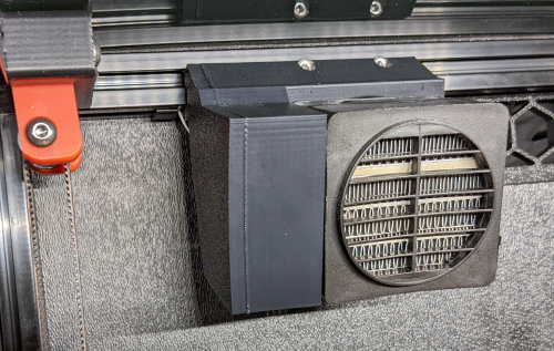
Trident Chamber Heater Mount
I wanted to reach ABS/ASA temperatures faster, and be able to maintain 55-60°C for those larger warp-prone prints, so I designed this chamber heater mount.
If you're going to attempt this, make sure to use a temperature fuse to protect your printer (and your house) from burning down in the event of failure/over-heating.
I used 2x 3mmx5mm long heatserts inserted from the front, and 3mmx12mm screws to attach the heater.
4x 3mm t-nuts and 4x 3mmx10mm screws are required for mounting the bracket.
I used this 120VAC 250W heater (with 12VDC fan): https://www.amazon.ca/dp/B07NYX5DKD?psc=1&ref=ppx_yo2ov_dt_b_product_details
I used this SSR: https://www.amazon.ca/dp/B06WLNHPWK?psc=1&ref=ppx_yo2ov_dt_b_product_details
I loosely followed the chamber heater post from @ahough, and this would've been way harder (nigh impossible) without their post and the comments section. Notable mention goes out to @Dousi as well, since I copied and modified their config example to use as my own.
I hope the configs below help someone else along their way.
********
******** Here is my chamber heater section within my printer.cfg file:
********
#####################################################################
# CHAMBER HEATER
#####################################################################
[thermistor chamber_thermistor] #define "chamber_thermistor" characteristics
temperature1: 25
resistance1: 100000
beta: 3950
[thermistor heater_thermistor] #define "heater_thermistor" characteristics
temperature1: 0.0
resistance1: 32116.0
temperature2: 40.0
resistance2: 5309.0
temperature3: 80.0
resistance3: 1228.0
[temperature_sensor heater_temp] #this is the temp sensor for the 10K probe inserted in the heater core
sensor_type: heater_thermistor #use temp sensor characteristics as defined in "heater_thermistor"
sensor_pin: PA2 #Manta 8P temp sensor input pin. This temp probe is glued to the heater core with UV resin
min_temp: -100 #set minimum temp before error/shutdown
max_temp: 140 #SAFETY max heater core temperature, printer will shutdown above this temp
[heater_generic chamber_heater] #setup chamber heater
heater_pin: PE3 #Manta 8P heater output pin to SSR. This temp probe is mounted near the top of my chamber
sensor_type: chamber_thermistor #use temp sensor characteristics as defined in "chamber_thermistor"
sensor_pin: PA1 #Manta *P temp sensor input pin
control: watermark #use watermark control method (on/off)
max_delta: 0.1 #set the delta temp to energize/deenergize chamber heater
max_power: 1.0 #set maximum power of heater 1.0 = 100%
min_temp: -100 #set minimum temp before error/shutdown
max_temp: 70 #SAFETY max chamber temperature, printer will shutdown above this temp
pwm_cycle_time: 0.01666 #Set this to avoid room lights flickering on higher power heaters. This value works well for 60Hz power. 0.1 is 10Hz
[verify_heater chamber_heater] #setup chamber heater verification parameters
max_error: 120
check_gain_time: 240
hysteresis: 5
heating_gain: 1
[heater_fan heater_fan] #setup fan attached to back of chamber heater
pin: PE4 #Manta 8P fan output pin. Jumper selected for 12V
max_power: 1.0 #set maximum power of fan 1.0 = 100%
heater: chamber_heater #when "chamber_heater" is ON fan will be ON
heater_temp: 30 #fan will turn off below this level
#####################################################################
# MACROS
#####################################################################
[gcode_macro M191]
gcode:
{% set S = params.S | default(0) | float %}
SET_HEATER_TEMPERATURE HEATER=chamber_heater TARGET={S}
M118 Chamber heating to {S}C
M118 Waiting for chamber heating...
TEMPERATURE_WAIT SENSOR="heater_generic chamber_heater" MINIMUM={S}
M118 Chamber heating {S}C is done.
********
******** I also run Ellis' bedfans, and modified bedfans.cfg, "Command overrides" section to the below:
********
############ Command overrides ############
# Override, set fan speeds to low and start monitoring loop.
[gcode_macro SET_HEATER_TEMPERATURE]
rename_existing: _SET_HEATER_TEMPERATURE
gcode:
# Parameters
{% set HEATER = params.HEATER|default("None") %}
{% set TARGET = params.TARGET|default(0)|int %}
# Vars
{% set THRESHOLD = printer["gcode_macro _BEDFANVARS"].threshold|int %}
{% if HEATER|lower == "extruder" %}
M104 S{TARGET}
{% elif HEATER|lower == "heater_bed" %}
M99140 S{TARGET}
{% elif HEATER|lower == "chamber_heater" %}
_SET_HEATER_TEMPERATURE HEATER=chamber_heater TARGET={TARGET}
{% else %}
{action_respond_info("Heater %s not supported" % HEATER)}
{% endif %}
# Set fans to low if heater_bed temp is requested above threshold temp, and kick off monitoring loop.
{% if HEATER|lower == "heater_bed" %}
{% if TARGET >= THRESHOLD %}
BEDFANSSLOW
UPDATE_DELAYED_GCODE ID=bedfanloop DURATION=1
{% else %}
BEDFANSOFF
UPDATE_DELAYED_GCODE ID=bedfanloop DURATION=0 # Cancel bed fan loop if it's running
{% endif %}
{% endif %}
********
******** II then modified my PRINT_START macro to include the chamber heater stuff as seen below:
********
[gcode_macro PRINT_START]
# Use PRINT_START for the slicer starting script - PLEASE CUSTOMISE THE SCRIPT
gcode:
EXCLUDE_OBJECT_DEFINE
BED_MESH_PROFILE load=default
# Load variables
{% set bed_temp = params.BED|default(60)|int %}
{% set extruder_temp = params.EXTRUDER|default(230)|int %}
{% set CHAMBER_TEMP = params.CHAMBER|default(20)|float %}
M104 S150 #start nozzle heating, keep below oozing temp
M117 Extruder Heating...
M140 S{bed_temp} #set bed temp to "bed_temp" and move on
M117 Bed Heating....
M190 S{bed_temp} #allow bed to get up to temperature
M117 Heating Chamber...
M191 S{CHAMBER_TEMP}
G90 #Use absolute coordinates
M117 Homing...
G28
M117 Adjusting Z Tilt...
Z_TILT_ADJUST
G28
M117 Calibrating Bed Mesh...
BED_MESH_CALIBRATE
M117 Waiting for Extruder to Reach Printing Temperature...
M109 S{extruder_temp}
G92 E0 #Reset exruder
M117 Purging Filament...
ADAPTIVE_PURGE
M117
********
******** I use CURA and this is my Start Gcode as defined within Cura:
********
;Nozzle diameter = {machine_nozzle_size}
;Filament type = {material_type}
;Filament name = {material_name}
M204 P500.00 R1000.00 T500.00 ;Setup Print/Retract/Travel acceleration
M220 S100 ;Reset Feedrate
M221 S100 ;Reset Flowrate
M117
PRINT_START EXTRUDER={material_print_temperature_layer_0} BED={material_bed_temperature_layer_0} CHAMBER={build_volume_temperature}
52 downloads
-
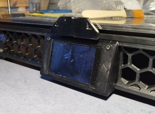
MKS TS35 Screen Front Panel
A front mount for MKS TS35 screen for the Voron Trident machine. It was designed as drop in replacement of Mini 12864 holder and has only one single printed part.
The MKS TS35 is larger than the Mini 12864 one, so the panel is 4mm taller and slightly sloped. This should not be a problem neither for bottom panel sheet nor for doors.
There are two versions:
a 117 mm width which is default Voron Trident size a 122 mm width which help me to reduce gaps between front panel components. Please choose whichever option suits you best.
The part should be printed with Voron recommended settings. Before installing the display, please remove two small supports near the bottom clip and check the size of the window cut (the display has a fairly tight fit). The display is secured with two M3 bolts/nut of suitable length (e.g. M3x8).
13 downloads
(0 reviews)0 comments
Updated
-
v2.4 Chamber Heater
I was having trouble getting my enclosure temperatures above 45C to achieve my optimum print settings. This is the solution I came up with to solve my enclosure temperature issues. I'm running a Fystec Spider v1.1, so your printer config would likely differ. I'm also using a Hartk v4.0 PCB that has an integrated chamber thermistor. I've included my settings for this as well, but you may need to change this up if you use a different thermistor for enclosure temperature readings.
I hope this is helpful for someone. I couldn't find a lot of solutions out on the net that could get me up and going with a setup like this, so it was a lot of trial and error to get to this point. Let me know if you have any comments or suggestions that can help me make this thing better!
How I set things up:
I removed the fan from the PTC heater and inserted a 100K NTC thermistor into one of the bordering fins on the heater core. I then filled the remaining gap in the fin with thermal grease and reattached the fan. I added a thermal fuse to make sure the power would get cut if the temperatures get out of hand from a bad config or faulty piece of hardware. First I drilled a 1/8" hole next to the center ground pin, rivetted the fuse to the heater's core, and applied thermal grease between the fuse body and the heater core. I then moved the ground wire to run from the fuse rather than the tab. Once I wired this up, I ran the temperatures up past the fuse limits to verify things fail safely as expected. I then replaced the fuse after test failed as expected. I extended all of the wiring with solder connections to make sure it would be long enough reach each wire's intended destination, and capped each connection with heat shrink. I mounted the PTC heater to the printed PTC heater mount and ran the wires to the wiring compartment. I installed the Omron relay, and ran a 24v output from my controller to the relay's 5-24v input. I then routed 110v AC to the other end of the relay on the hot lead. I finished up the wiring by hooking up the 12v line for the heater fan and the heater thermistor to the controller board. (Note: my chamber thermistor was already installed on my toolhead's PCB) I updated my printer.cfg and ran a bunch of tests on the heater to make sure it was functioning properly. BOM:
Electronics:
- PTC Heater w/ Fan x1 - Item on Amazon
- NTC 100k thermistor - Item on Amazon
- 120C Thermal Fuse - Item on Amazon
- Omron 5-24v Relay - Item on West3D
Printed Parts:
- Printed PTC Heater Mount x1
Miscellaneous:
- M3x8mm SHCS x2
- M3 T-nut x2
- 18awg stranded wire ~2 meters
- 22awg stranded wire ~2 meters
- 1/8" Rivet x1
- Appropriate connectors for you controller board
Changes to printer.cfg:
###################### ### Chamber Heater ### ###################### [heater_generic chamber_heater] heater_pin: PC8 sensor_type: Generic 3950 sensor_pin: PC2 control: watermark max_power: .5 min_temp: 0 max_temp: 110 [verify_heater chamber_heater] max_error: 120 check_gain_time: 120 hysteresis: 5 heating_gain: 2 ########################## ### Chamber Heater Fan ### ########################## [heater_fan chamber_heater_fan] pin: PB6 max_power: 1.0 heater: chamber_heater heater_temp: 40.0 # fan will turn off below this level ############################# ### Enclosure Temperature ### ############################# [thermistor chamber_thermistor] temperature1: 25 resistance1: 10000 beta: 3950 [temperature_sensor enclosure_temp] sensor_type: chamber_thermistor sensor_pin: PC1 min_temp: 0 max_temp: 80
Macro:
You can run this and immediately start your print. The print wont actually start until the specified chamber temperatures are reached.
[gcode_macro CHAMBER_TEMP_WAIT] gcode: {% if params.MIN_TEMPERATURE and params.MAX_TEMPERATURE and params.MIN_TEMPERATURE|float > params.MAX_TEMPERATURE|float %} {action_raise_error("Chamber Temp Wait: MIN_TEMPERATURE must be less than or equal to MAX_TEMPERATURE Use: - CHAMBER_TEMP_WAIT MIN_TEMPERATURE=[0..80] - CHAMBER_TEMP_WAIT MAX_TEMPERATURE=[0..80] - CHAMBER_TEMP_WAIT MIN_TEMPERATURE=[0..80] MAX_TEMPERATURE=[0..80]")} {% elif params.MIN_TEMPERATURE and params.MIN_TEMPERATURE|float > -1 and params.MIN_TEMPERATURE|float < 81 %} {% if params.MAX_TEMPERATURE and params.MAX_TEMPERATURE|float > -1 and params.MAX_TEMPERATURE|float < 81 %} TEMPERATURE_WAIT SENSOR="temperature_sensor enclosure_temp" MINIMUM={params.MIN_TEMPERATURE|float} MAXIMUM={params.MAX_TEMPERATURE|float} {% else %} TEMPERATURE_WAIT SENSOR="temperature_sensor enclosure_temp" MINIMUM={params.MIN_TEMPERATURE|float} {% endif %} {% elif params.MAX_TEMPERATURE and params.MAX_TEMPERATURE|float > -1 and params.MAX_TEMPERATURE|float < 81 %} TEMPERATURE_WAIT SENSOR="temperature_sensor enclosure_temp" MAXIMUM={params.MAX_TEMPERATURE|float} {% else %} {action_raise_error("Chamber Temp Wait: invalid usage Use: - CHAMBER_TEMP_WAIT MIN_TEMPERATURE=[0..80] - CHAMBER_TEMP_WAIT MAX_TEMPERATURE=[0..80] - CHAMBER_TEMP_WAIT MIN_TEMPERATURE=[0..80] MAX_TEMPERATURE=[0..80]")} {% endif %}
Updates:
- I added a photo of how this is wired up in the wiring compartment. The boxes with the text in the photo represent the components of the heater that are in the chamber of the printer.
- I have included the macro to wait for chamber to reach temps before starting a print.
- I have attached the heater mount's fusion 360 file for others to be able to easily make edits to the chamber heater mount
Chamber Heater Mount v2.f3d
630 downloads
- chamber heater
- heater
- (and 1 more)
-
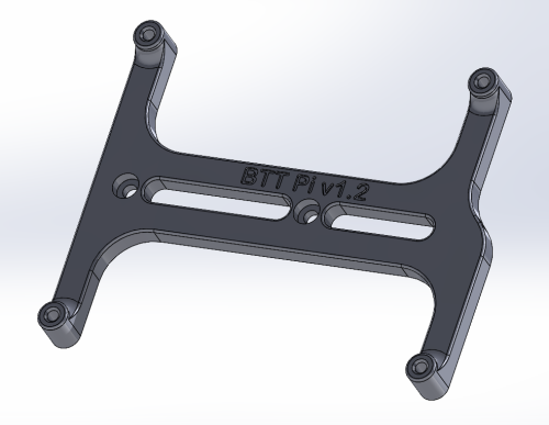
Voron BTT Pi v1.2 Din Rail Mount
This is a design based off the Voron Pi mount for the BTT Pi v1.2 to use on Voron printers where you want to use the BTT Pi instead of the regular Pi boards.
58 downloads
(0 reviews)0 comments
Submitted
.thumb.jpg.2c879d60315f8d86612bb06a137c204a.jpg)

.thumb.png.d79cf784623134eccdc7f2a1d383206b.png)
.thumb.png.ccacec25ec2c6981985cafe50328c3e3.png)
-
Most Actively Discussed Mods
-
Hottest Files!